

A aparat de sudură pentru perete video combines and arranges multiple sources on a display canvas; an LED controller sends the resulting pixel data to the receiving cards in an LED wall. A straightforward single-source wall may need only a suitable controller or all-in-one processor. A control room with several simultaneous windows may also need splicing, either in a separate processor or in one chassis that supports both functions.
This distinction matters to AV integrators specifying a direct-view LED system. A quotation that names a chassis but omits its input cards, sending outputs, pixel loading and source layouts cannot prove that the proposed signal path will work. Start with what operators must see, then map the required hardware and test it with the actual wall.
The comparison below addresses fixed commercial and event systems, not tiled LCD walls. It explains the roles, a practical decision rule and the information to include in a system brief. Product capabilities are configuration-specific; the examples do not imply that every processor or controller supports every feature.
1. Video wall splicer and LED controller: different jobs
A aparat de sudură pentru perete video handles the composition of a picture. It can place inputs in separate windows, scale them and recall layouts when the specified model and cards support those functions. An LED sending controller maps the finished picture to output ports and transmits data to compatible receiving cards inside the cabinets. The modules display the pixels; they do not choose the window layout.
01. Follow the signal, not the product label
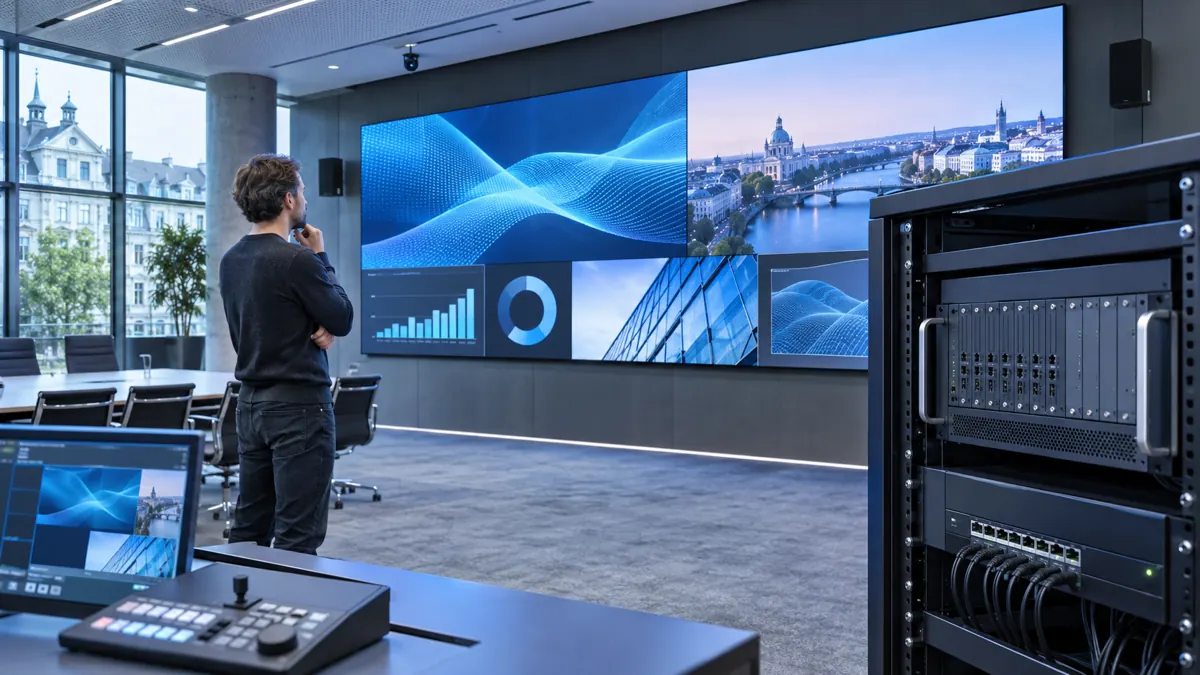
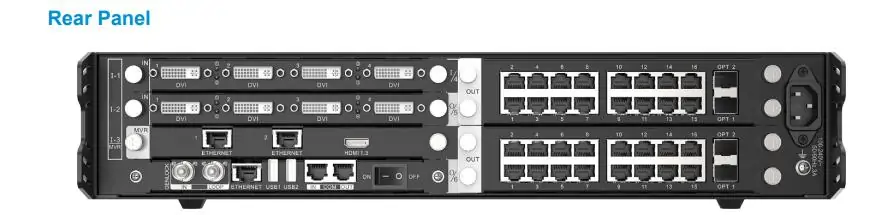
In a simple path, a laptop or media player feeds an LED controller, which distributes the image across the cabinets. In a multi-source path, a aparat de sudură pentru perete video accepts several feeds and produces the composed canvas before LED sending. The two roles may occupy separate boxes. Some modular products combine them when fitted with suitable sending cards. The Ghid de configurare NovaStar H2 describes one such modular example; the exact card set determines its capabilities.
Do not infer function from a front-panel photo. A rack chassis may have unused slots, and a connector may be a loop output rather than an independent input. Ask for a block diagram naming every source, card, output and cabinet chain. The diagram should show which device creates the final canvas and which sends it to the wall.
02. Separate input resolution from wall resolution
A processor accepting a 4K source does not make a smaller LED wall native 4K. The physical matrix follows the assembled cabinet grid and pixel pitch. A 3,840 × 2,160 feed can be scaled to a wall with fewer pixels; that is a processing function, not extra display detail. Use the Ghid de rezoluție a afișajului LED to calculate an initial pixel target, then request the exact cabinet map.
03. Check where timing and audio are handled
Source composition is only part of the signal design. Ask which device sets output timing, where source audio is routed, and how a change of input affects the picture. A presentation room may need a clean switch between a laptop and a room PC; a live production team may need the camera feed to stay aligned with sound. The display hardware alone does not establish that behavior. Put the required switching sequence in the operating brief and have the integrator test it with the intended sources. If audio is handled by a separate system, identify its connection and owner on the signal diagram rather than assuming it follows the video automatically.
2. When does an LED wall need a video wall splicer?
Specificați a aparat de sudură pentru perete video when the operating brief requires several independent sources to appear at once, flexible window positions, rapid preset changes or source routing across a large custom canvas. If one player supplies one finished picture and the chosen LED controller can accept, scale and send it within its documented limits, a separate splicer may add complexity without solving a requirement.
| Sarcină operațională | Likely starting architecture | Verificare înainte de cumpărare |
|---|---|---|
| One scheduled full-wall image from one player | Compatible LED controller or all-in-one processor | Input format, native wall pixels, output-port loading and backup plan |
| Several live sources in independently sized windows | Splicing function plus LED sending, integrated or separate | Simultaneous inputs, supported layers, source timings and preset recall |
| Large canvas spanning multiple sending domains | Configured processor and sending architecture | Pixel map, synchronization, port allocation and recovery behavior |
| Critical control-room display | Project-specific splicing, control and redundancy design | Failure tests for source, processor, link and power paths |
This table is a starting point, not an equipment compatibility list. For example, a source switcher may solve a requirement to show one of several feeds full-screen; it does not automatically provide simultaneous windows. Conversely, an all-in-one processor can make a separate aparat de sudură pentru perete video unnecessary if its documented input, layer and sending functions meet the entire brief.
01. Count simultaneous sources, not just sockets
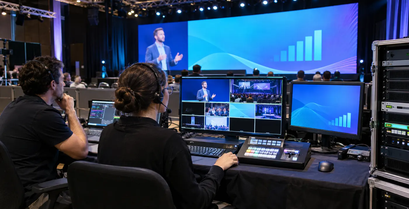
List each computer, camera, player and remote feed that must remain available at the same time. For each one, state the connector, resolution, frame rate, color format and whether audio must follow it. Then draw the proposed on-screen windows. A aparat de sudură pentru perete video with many physical connectors can still have limits on concurrent channels, layers or particular input modes. Check the current specification for the exact input cards and firmware quoted.
02. Decide who will operate the layouts
A venue operator may need only two approved presets. A control-room team may need frequent source changes and restricted user access. Document who can edit, recall and recover layouts, and whether the control interface works on the site network. If a layout must survive power loss, verify the restart sequence. A feature listed in a brochure is useful only if the delivered configuration and staff workflow support it.
03. Translate a use case into a testable layout
Consider a hypothetical operations wall that shows a camera feed, a map and a dashboard at the same time. The brief should state the minimum readable dashboard text, the position and aspect ratio of each window, and whether an operator can enlarge the camera without hiding an alarm. A brochure statement such as “supports multiple windows” cannot answer those questions. In a single-source lobby, by contrast, the content team could combine the same elements in one finished video or signage canvas before it reaches the LED controller. The right architecture depends on whether operators must change the sources independently during normal use, not merely on the number of pictures visible in a sample design.
3. Specify the complete LED signal path
A usable request for quotation identifies the wall, sources, processor, sending stage, receiving cards and physical links as one system. For the wall, provide buildable width and height, pixel pitch, cabinet model and native pixel matrix. For each source, specify its actual output format. For the aparat de sudură pentru perete video, state the simultaneous window count and sample layouts rather than asking vaguely for “multi-screen support.”
Port capacity deserves its own check. Divide the wall into cabinet chains, record the pixels assigned to each output and compare them with the selected controller or sending-card limits. Allow for the required cable route and any specified backup path. Never treat a chassis-level maximum as the capacity of every card or port. The Ghid pentru splicer H9 illustrates how card choices and layer modes affect a modular system.
01. Confirm formats from source to screen
Ask the integrator for a source schedule that records connector type, resolution, frame rate, color format, cable length and any conversion device. Confirm the display’s native pixel map separately. The processor may accept a source but still scale, crop or letterbox it in a way that makes small information hard to read. Test the actual computer output and its EDID negotiation, especially when a laptop may be unplugged and replaced during a meeting. For long signal runs, specify the transport method and the point at which a failed link can be isolated. These checks prevent a familiar problem: each product appears compatible on paper, but the complete chain does not reproduce the intended image after a source change.
02. Compare complete quotation scopes
For procurement, request a line-item equipment schedule. It should distinguish the aparat de sudură pentru perete video chassis, installed input and output cards, LED sending hardware, receiving-card compatibility, licenses if applicable, signal converters, cables and spare parts. Ask the supplier to state which functions are included and which require optional cards or services. The lowest chassis price may not be the lowest working-system price.
Require each bidder to price the same source count, wall matrix and operating presets. Separate equipment supply from installation, programming, training and on-site support so the totals can be compared. If one proposal combines splicing and sending in a single unit while another uses two devices, compare the complete working path and its recovery plan, not the number of boxes. Also identify who owns configuration files and who can restore service after a card failure. A lower upfront total may require additional conversion hardware or specialist labor later. Request the final card schedule before treating either proposal as a fixed scope; no universal price follows from the architecture alone.
4. Verify the system before handover
Commission the aparat de sudură pentru perete video against the approved operating brief. Feed every required source at its planned timing, build the real window layouts and confirm the complete wall pixel map. Test the smallest text from the nearest operator position and verify that the processor does not crop a required edge. If cameras film the wall, test with the intended shutter, frame rate and brightness; a refresh-rate figure alone cannot guarantee clean footage.
Then test recovery. Remove one source, reboot the processor and interrupt a planned signal link under controlled conditions. Record what operators see, how they restore the approved layout and which settings or files must be backed up. For critical systems, the project team should define acceptable recovery behavior before equipment is ordered. An optional redundant power module is not proof that the complete signal path has no single point of failure.
Make the acceptance record specific enough for a second technician to repeat it. Note the source file or live feed, input port, window preset, wall brightness, ambient lighting and observer position for each visual check. Record the observed result and any correction before sign-off. For a camera-facing installation, save short test clips made with the intended production camera settings, while recognizing that another camera may behave differently. For a continuously operated room, repeat the checks after a planned restart and after restoring the approved configuration backup. This turns “looks good” into an agreed result that the owner can verify after maintenance.
Handover should include the final cabinet map, port assignments, firmware versions, processor presets, configuration backups and a labeled cable schedule. Save a known-good test file and note the display brightness setting used for acceptance. The service team can then reproduce the approved result after a card replacement rather than rebuilding the system from memory.
5. Întrebări frecvente
01. Is a video wall splicer always required for an LED wall?
No. An LED wall needs a compatible sending and receiving path, but a separate aparat de sudură pentru perete video is unnecessary when a suitable controller or all-in-one processor handles the required single-source picture, pixel load and output mapping. Multiple independently placed sources are a reason to assess splicing.
02. Can one chassis act as both splicer and LED controller?
Yes, some modular systems can perform both roles with the correct cards and configuration. Check the installed card list, simultaneous source limits, sending capacity and receiving-card compatibility. A bare chassis name does not confirm those functions.
03. Does 4K input mean the LED wall shows native 4K?
No. Input format and the wall’s physical pixel matrix are different. A processor may scale a 4K image to a smaller LED canvas. Specify the exact assembled width × height in pixels and confirm the final cabinet map.
04. What evidence should an integrator request at handover?
Ask for the as-built signal diagram, card schedule, cabinet and port map, preset exports, firmware records, labeled cables and a witnessed recovery test. Those records make future maintenance and replacement more predictable.
6. Plan the Equipment List for Your Wall
Send the proposed wall dimensions, nearest viewing distance, cabinet or pitch preference, all simultaneous source formats, example layouts and operating schedule to the display supplier. Include site power, rack location, cable distances and any recovery requirement. EagerLED can review the display-side configuration and the information needed to quote a compatible system. Discuss your LED wall requirements with EagerLED.