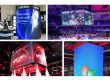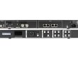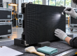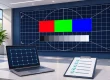


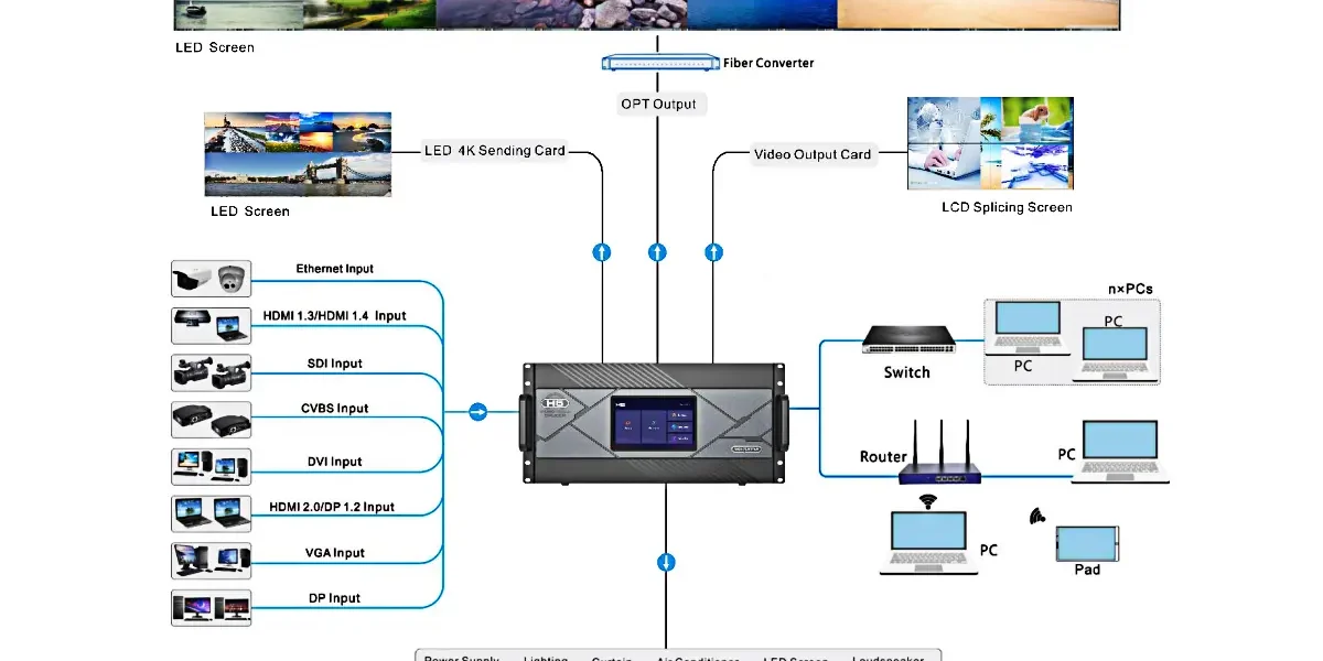
LED wall EDID tells a connected video source which input formats the receiving device advertises. It does not change the LED wall’s physical pixel count, automatically arrange cabinets, or guarantee that a picture will fill the screen. An AV integrator should treat input timing, image scaling, and cabinet mapping as three separate parts of the design.
This distinction matters before ordering a processor for a custom-sized display. A laptop might report a 1920 × 1080 display while the installed cabinets form a different pixel matrix. That can be a valid configuration, provided the source, processor, and content layout are planned together.
This explanation is for AV integrators specifying a fixed indoor installation. It focuses on the meaning and limits of EDID, with a worked example and the questions to resolve before approving a control-system quotation.
What LED wall EDID actually describes
EDID stands for Extended Display Identification Data. It carries display capability information that a source can use when selecting its video output. In an LED installation, the device facing the laptop may be a processor input, a switcher, or an extender with its own EDID management. The laptop does not necessarily receive a description of the physical LED cabinet layout.
Extron’s technical explanation of EDID describes this capability exchange and the problems that can arise when the source cannot read it correctly. The practical implication is simple: record what the source is being told, then separately check what signal it actually sends. An advertised mode and a measured incoming signal are different evidence.
Think of LED wall EDID as an input-format agreement. It helps establish a usable video connection, but the rest of the system still has to place that video on the correct pixels. A successful connection alone does not prove that a spreadsheet, camera feed, or presentation has the intended proportions.
Keep three pixel dimensions separate
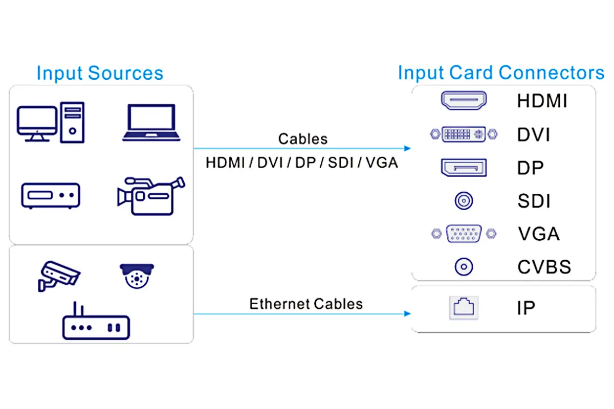
A clear LED wall EDID specification distinguishes the artwork canvas, the incoming video raster, and the installed wall matrix. Write all three as width × height in pixels. A label such as “4K compatible” is too broad to describe their relationship.
- Artwork canvas: the dimensions used to create the slide, video, or media-server composition. Content may already contain borders or multiple regions.
- Input raster: the active video dimensions received at the selected processor connector. Confirm the accompanying frame rate and signal format.
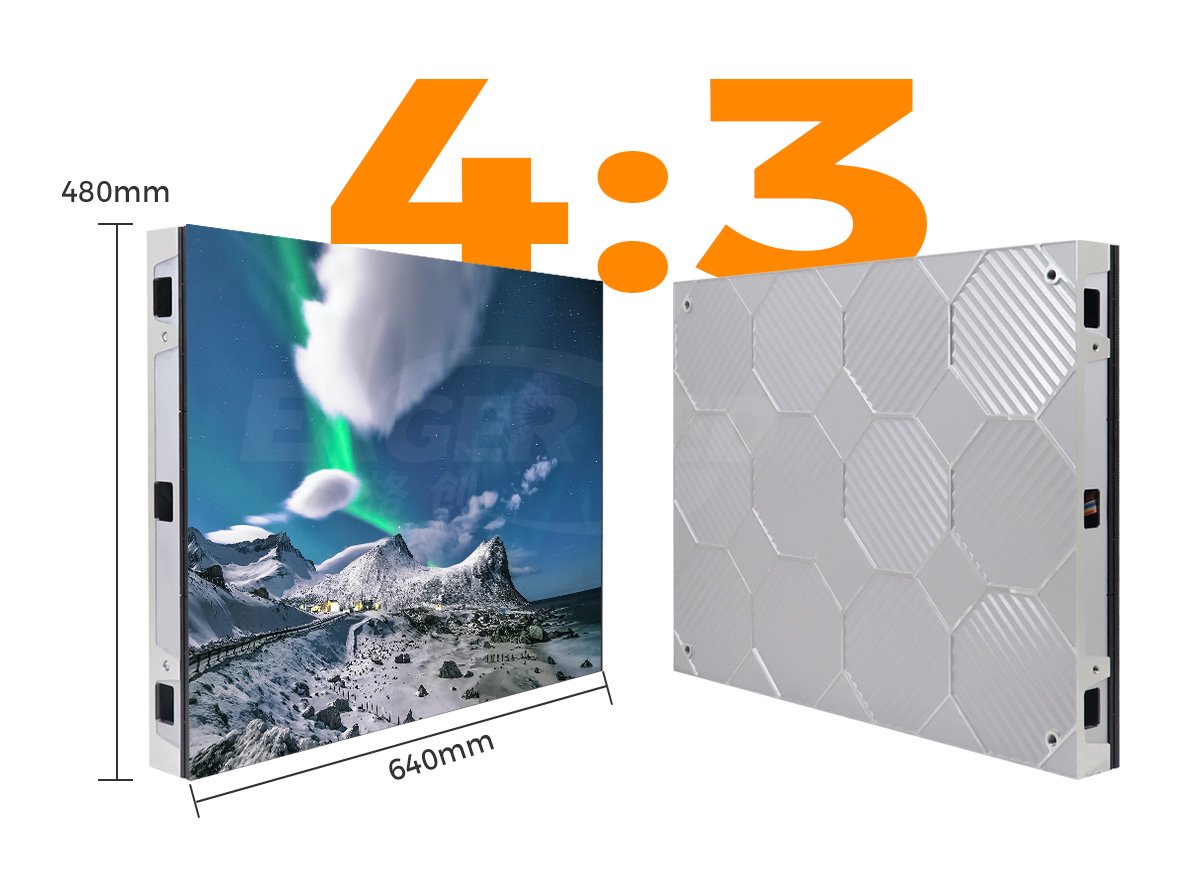
- Native wall matrix: the physical pixel columns and rows supplied by the assembled cabinets. Calculate it from the exact cabinet pixel dimensions and arrangement.
The processor may scale or crop the incoming raster and position it within a screen canvas, depending on its supported functions and operating mode. Cabinet mapping then determines where those image regions appear. Changing the advertised input format does not substitute for either operation.
EagerLED'S LED ekran çözünürlük kılavuzu explains the distinction between physical pixels and accepted input resolution. Use it when documenting the wall matrix, then add the input-side information to the same project drawing. This keeps a controller’s headline input capability from being mistaken for the delivered screen resolution.
A custom wall and a standard video signal
Consider a hypothetical wall with ten cabinet columns and six rows. Assume each cabinet contains exactly 192 × 192 pixels. The assembled display therefore has 1920 × 1152 pixels. These are example dimensions, not specifications for a particular EagerLED ürün.
Now suppose the agreed source signal is 1920 × 1080. The wall is taller relative to its width than that 16:9 signal. LED wall EDID cannot remove that difference in shape. The project needs an explicit image-placement decision:
- Preserve the full picture: a centered, unscaled 1920 × 1080 image leaves 72 unused pixel rows, or 36 above and 36 below.
- Fill by stretching: increasing the image height to 1152 changes vertical proportions. The height increases by approximately 6.7%, so circles and faces can look taller.
- Fill while preserving proportions: uniform scaling to 1152 pixels high produces a 2048-pixel-wide picture. A centered crop removes 64 pixels from each side of that scaled image.
These calculations describe image geometry, not a promise that any particular controller offers every option. Confirm the available scaling and cropping modes before selecting hardware. Alternatively, create content for the wall’s exact canvas and verify a supported method of transporting and mapping it.
The choice belongs in the content brief. A border may be acceptable for presentations but undesirable for architectural graphics. Cropping may work for a background video yet remove an essential label from a data dashboard. Decide using representative content rather than a full-screen landscape photograph.
Why custom EDID has limits
A custom LED wall EDID does not add bandwidth or processing capacity. The source, adapter, cable path, input connector, and processor must all support the requested signal. Maximum width, maximum height, frame rate, color format, and other timing requirements need to be considered together.
NovaStar’s MX30 User Manual V1.5.0 provides a useful model-specific example: its external-source EDID menu applies to HDMI1, HDMI2, and DP, with standard and custom resolution choices. The manual treats input information and screen configuration separately. That example should not be turned into a universal menu path for every controller or interface.
The H Series User Manual V1.5.0 likewise distinguishes standard, custom, and advanced EDID settings. It reserves advanced timing work for people familiar with those parameters. For a quotation, request confirmation of the exact required signal rather than inferring compatibility from a maximum pixel count.
What to verify in a demonstration
Ask the supplier to demonstrate the complete proposed signal path with your normal source device and representative content. A useful LED wall EDID demonstration records the selected input, its advertised format, the detected incoming signal, the image-placement settings, and the wall’s native matrix.
Include the actual docking station, adapter, extender, or switcher if the finished room will use one. A direct laptop-to-processor test is useful for comparison, but it does not validate the equipment inserted between them. Extron documents EDID management in switching and distribution systems; the upstream source can be influenced by how those intermediate devices handle capability information.
Use a labeled border, circles, small text, and numbered regions in the test content. These make missing edges, distorted proportions, and misplaced areas easier to identify. Agree which content should fill the wall and which should retain its original aspect ratio. Keep a photograph and LED wall EDID record with the accepted source settings for each case.
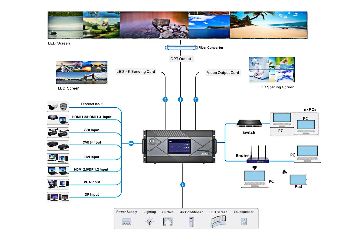
For hardware background, see the H5 processor overview. Consult the matching manual for the supplied hardware and software revision; an illustration of a connector family does not establish the capabilities of an installed card.
Match the symptom to the right question
LED wall EDID is one possible part of an image problem. The table below is a discussion aid for a demonstration or support call, not a diagnosis from appearance alone. It helps collect evidence before anyone changes a working cabinet configuration.
| Gözlem | Toplanacak kanıtlar | Çözülmesi gereken soru |
|---|---|---|
| The required source mode is unavailable | Advertised EDID, source output options, adapter identity | Does the full input path support and advertise the required timing? |
| The processor detects video but edges are missing | Input dimensions, crop values, layer position, test border | Where is the picture being cropped or placed outside the visible canvas? |
| The picture has borders | Original artwork, active image area, aspect-ratio settings | Are the borders in the content or introduced by image placement? |
| Individual cabinet regions repeat or appear out of order | Numbered test pattern and actual connection map | Does the screen mapping match the installed arrangement? |
| Only one source or adapter combination fails | Working and failing signal formats with the same processor input | Which part of that source path changes compatibility? |
Sık Sorulan Sorular
Does a 60 Hz EDID setting mean the LED modules refresh at 60 Hz?
No. Input frame timing and the LED module’s drive refresh specification describe different operations. Record both separately. A high module refresh figure does not prove that the source is delivering a higher video frame rate.
Does EDID replace the receiving-card configuration file?
No. The receiving-card file concerns the cabinet or module configuration, whereas EDID concerns information presented to a video source. Keep each record with its intended hardware. EagerLED'S RCFG and RCFGX explanation describes the receiving-card side and its compatibility checks.
Can the same screen use different input formats for different sources?
Potentially, if the controller and the rest of the signal path support the proposed formats. Document the accepted combinations and image-placement settings for each source. Do not assume that a successful laptop test also validates a camera, playback appliance, or conference-room dock.
Should we buy a separate EDID emulator immediately?
First establish the actual problem and the capabilities already present in the processor, switcher, or extender. An emulator addresses capability communication; it does not create missing scaling functions, repair cabinet mapping, or expand an input’s supported bandwidth.
Sinyal yolunun tamamını belirtin.
Before approving the system, put the wall matrix, source list, required input formats, intermediate equipment, and intended image placement on one brief. Include examples of the smallest text and the content that must remain uncropped. Ask for the supported configuration and acceptance demonstration to be included with the proposal.
For help matching LED wall EDID requirements to a display project, UAF ile EagerLED with your pixel map and source-equipment list. State whether standard video formats are acceptable or whether the application needs a verified custom input format.