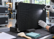


A front service LED module can be inspected and replaced from the viewing side of an LED wall, making maintenance practical where rear access is limited. Keeping it reliable involves more than removing dust: the display face, retention hardware, power connections, signal path and cabinet environment all affect the final image.
To maintain a front service LED module, record the symptom, isolate power for hands-on work, clean with approved tools, inspect cooling and connections, and test the reassembled display. Remove a module only when inspection or diagnosis requires it. A dark area may come from a shared power or data fault rather than the visible module itself.
This guide helps owners, installers and maintenance teams plan care for a front maintenance LED display. It explains seven practical steps, fault checks, service scheduling and spare-part decisions. Use the installed product’s manual for release tools, electrical limits, cleaning methods and safe access; front-service construction varies between models.
1. What Front Maintenance Means for Your LED Display
A front maintenance LED screen allows serviceable modules to be released from the display face. A front service LED module may use magnetic retention, mechanical locks or another manufacturer-defined arrangement. The access method does not identify its pixel pitch, LED packaging or weather resistance.
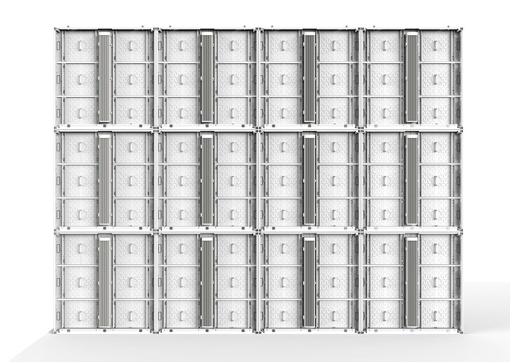
Confirm the full service path before planning a repair. A front-removable module does not necessarily make every power supply, receiving card or cable replaceable from the front. Also check whether trim, furniture or structural framing blocks the tool or removal path. The access drawing should show how a technician reaches the opening and where the removed part is supported.
| Check | Front service | Rear service |
|---|---|---|
| Access direction | Modules are removed from the viewing side. | Technicians access components from behind the screen. |
| Installation space | Useful where rear access is restricted; keep front working space available. | Requires a suitable rear access route and working area. |
| Parts you can reach | Verify access to modules, power supplies, receiving cards and cables separately. | Verify rear doors, obstructions and the removal path for each part. |
| Cooling and safety | Follow the cabinet ventilation and isolation requirements. | The same checks apply; rear access alone does not solve cooling or safety issues. |
For a wall-mounted installation, front access can remove the need for a rear working aisle, but it does not eliminate ventilation clearance. For rental displays, check the service method on the actual cabinet: similar-looking rental panels may use different access arrangements. Keep the correct removal tool with each screen family so technicians do not improvise under event-time pressure.
2. Seven Front Service LED Module Maintenance Steps
01. Record the image fault before opening the screen
Observe the front service LED module from a safe position while the screen operates normally. Identify whether the defect affects a single pixel, a horizontal line, one module, one cabinet or several cabinets. Record its coordinates on a cabinet map, the time it appears and whether brightness, content or warm-up changes the symptom.
When there is no sign of electrical damage or moisture, use supported red, green, blue, white, black and grayscale test patterns to separate a source-content issue from a display problem. Record both the test pattern and normal playback. A phone camera can introduce rolling bands, so compare the recorded effect with what a person sees directly before diagnosing flicker.
If a front service LED module is associated with smoke, a burning smell, water ingress or repeated protective-device tripping, stop operation and arrange qualified isolation and assessment. Do not continue test patterns to collect more evidence under those conditions.
02. Prepare isolation, ESD protection and service tools
Before touching a front service LED module, trained personnel should follow the site isolation procedure, identify all relevant power sources and verify the equipment is safe to work on. A black image or software shutdown is not electrical isolation. Observe the manufacturer’s discharge requirements and the site’s controls against accidental restart.
Prepare the specified removal tool, suitable access equipment, protective trays and an appropriate electrostatic discharge (ESD) workstation. A magnetic lifter, vacuum tool and mechanical service key are not interchangeable. Confirm the tool’s compatibility with the module face and retention design, including any safety tether.
Keep the work area below an elevated screen clear, protect adjacent LEDs and arrange support for the released part. Do not let cables carry a module’s weight. If live measurements or power-supply work are necessary, assign them to personnel qualified for those tasks under the approved procedure.
03. Clean the front service LED module correctly
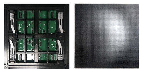
With power isolated, remove loose contamination using the method approved for the exact front service LED module. Exposed SMD LEDs can snag on cloth fibers or suffer damage from pressure. A COB or GOB coated face has different surface characteristics, but a coating is not permission to use household cleaners.
Where the manual permits, use a soft ESD-safe brush or a specified lint-free wipe. Do not spray cleaner into gaps or connectors. Avoid abrasive pads, unapproved solvents, pressure washing and improvised compressed air. If damp cleaning is permitted, follow the specified cleaner, application method and drying requirement before reassembly.
Distinguish loose dust from oily residue, salt deposits or signs of corrosion. If approved gentle cleaning does not remove the contamination, ask support for the next method instead of increasing force. Record the cleaning material used on the front service LED module so recurring surface damage can be traced.
04. Check cooling and outdoor weather protection
Inspect cabinet air paths and, where fitted, filters and fans. A front service LED module can overheat when surrounding trim or a cable bundle blocks airflow even if the visible face looks clean. Compare alarms and operating temperatures with the specified limits and the site’s established baseline; there is no universal safe cabinet temperature for every product.
On outdoor displays, check accessible gaskets, cable entries and drainage features for contamination or damage. Look for water tracks and corrosion rather than assuming the front surface tells the whole story. An ingress-protection rating describes the specified assembled product, not an open cabinet during maintenance.
Replace damaged sealing parts according to the manufacturer’s procedure. Do not block designed drains with improvised sealant. Keep affected equipment isolated after water ingress until qualified personnel establish the cause, assess damage and approve restart.
05. Separate power faults from signal faults
With the equipment isolated, inspect accessible front service LED module connectors for bent contacts, loose latches, heat discoloration or corrosion. Photograph and label cable routing before disconnection. Hold connector housings, release their latches correctly and avoid pulling on wires or repeatedly reseating parts without a diagnostic plan.
A dark front service LED module may have lost power, data or both. Use the installation map to identify shared power supplies and upstream signal connections. A fault covering several modules on one output points to a different investigation from a single damaged pixel. Receiving-card status indicators should be interpreted using that card’s manual.
Use approved cable pinouts, polarity and electrical ratings. Do not assume that all modules use the same DC voltage or increase supply output to disguise a dim area. Any required measurements must be compared with the exact product specification by a qualified technician.
06. Remove and replace only the confirmed suspect module
To remove a front service LED module, follow its documented release sequence and support it as the locks or magnets disengage. Do not pry against neighboring LEDs. Preserve safety tethers and disconnect power and data in the prescribed order. Put the part in a protective tray without loading the LED face or fragile edges.
Before fitting a replacement front service LED module, match the approved part number and hardware revision. Pixel pitch and physical dimensions alone are insufficient: driver ICs, scan configuration, connector orientation and electrical requirements may differ. Record the old and new serial numbers and keep the removed part labeled for diagnosis.
Check mating connectors and alignment points before seating the spare. Restore locks, retention hardware and seals without trapping cables. If the module will not sit flush with normal installation force, stop and inspect the fit; forcing it can damage connectors or adjacent pixels.

07. Verify the repair under realistic operating conditions
After closing the cabinet and completing the required checks, restore power in the prescribed sequence. Test the front service LED module with solid colors, low-gray patterns and normal moving content. Inspect seams, missing pixels, color uniformity and image stability from both service distance and normal viewing positions.
A replacement can light correctly yet remain visually different because of LED batch variation, aging or correction data. Confirm the approved receiving-card configuration and calibration process before adjusting brightness. Do not reset or update the whole system as a routine response to a local module fault; preserve a known-good configuration backup.
Observe the repaired front service LED module through the conditions that previously triggered the defect, within the product’s limits. Record which checks passed and any remaining mismatch. Returning the wall to service should depend on agreed acceptance criteria, not simply the absence of a black rectangle.
3. Troubleshooting a Front Service LED Module
The following table narrows the investigation; symptoms alone cannot identify a failed component. Before exchanging a front service LED module or cable, isolate power and confirm compatibility. Change one variable at a time so each result is meaningful.
| Symptom | First checks | Next decision |
|---|---|---|
| One module is black | Check its approved power and data connections and the upstream signal path. | A technician can test with one known-good compatible part at a time. |
| A row, column or block is abnormal | Compare supported test patterns; inspect data routing and configuration. | Persistent local faults may need driver, PCB or module diagnosis. |
| Several cabinets fail together | Check the common controller, network path and power distribution. | Investigate the shared path before replacing individual modules. |
| A spare looks brighter or a different color | Check part revision, LED batch, settings and calibration data. | Confirm approved compatibility and calibration with support. |
| Flicker appears after warming up | Check cooling, connector condition and power stability. | Have a technician investigate heat-related or intermittent faults. |
| Water, scorch marks or repeated tripping | Stop use and arrange safe isolation. | Require qualified assessment before restarting. |
For example, if an approved known-good cable restores a dark module, document that result before replacing additional parts. If a fault stays at the same location after a verified compatible replacement, investigate the local power, HUB interface and upstream signal path. Do not keep installing spare modules into a location with suspected electrical damage.
For isolated pixel defects, consult EagerLED’s LED screen dead-pixel diagnosis guide. Component-level LED or driver repair requires suitable equipment and skills; a front service LED module swap and PCB rework are different service tasks.
4. Maintenance Schedule and Service Records
Set the front service LED module maintenance schedule from the manufacturer’s requirements, operating hours, environment and fault history. The table is a planning framework, not a mandatory monthly or quarterly rule. A dusty public venue, controlled meeting room and coastal outdoor installation need different inspection decisions.
| When | What to check | What to record |
|---|---|---|
| Routine operating checks | Image quality, alarms, visible damage and abnormal noise. | Location, symptom and a photo when a change appears. |
| Planned service visit | Approved cleaning, airflow, accessible connections and retention hardware. | Findings, actions and the next inspection date. |
| After transport or an event | Module edges, locks, connectors and signs of moisture or impact. | Damage and parts needing inspection before reuse. |
| After severe weather or water exposure | Safe access, seals and possible ingress; qualified assessment where needed. | Exposure, affected cabinets and restart authorization. |
| After a repair | Mechanical fit, restored seals, test patterns and normal content. | Part numbers, configuration changes and test results. |
Assign a responsible person to each task and define what triggers escalation. Operators can record visible defects and alarms without opening the screen. Technicians handle isolated inspections and approved replacement work. After transport, inspect impact-prone edges and retention points before reuse; after water exposure, follow the assessment procedure before energizing.
A useful front service LED module record includes date, cabinet coordinates, model and revision, fault photos, operating conditions, parts changed, configuration filenames and final test results. Record “no fault reproduced” when appropriate rather than marking an unresolved intermittent problem as repaired. Comparing successive records helps reveal repeated failures in one power zone or recurring damage after handling.
5. Spare Modules and LED Display Maintenance Support
Order a spare front service LED module against the installed bill of materials and supplier confirmation. EagerLED’s LED display module range helps identify product families, but a catalog match does not establish interchangeability with an older installation.
| Match | Evidence to provide | Why it matters |
|---|---|---|
| Part and revision | Module label, cabinet model and order number | Identifies the approved hardware rather than a visually similar board. |
| Mechanical fit | Dimensions, retention method and connector positions | Prevents incompatible locks, mounting points or removal tools. |
| Electrical and data design | Specified supply, pinout, driver and scan information | Avoids mismatched power or signal interfaces. |
| Image configuration | Receiving-card model and approved configuration backup | Supports correct mapping and driver settings. |
| Visual matching | Batch reference, calibration information and screen history | Helps assess brightness and color blending after replacement. |
Stock quantities should reflect repair lead time and the consequence of downtime. Keep verified spares separate from failed or untested returns, and include approved cables or other common service parts where the project requires them. A spare front service LED module is useful only if the team also has the release tool, configuration files and access plan.
For EagerLED maintenance support and spare identification, provide the symptom map, label photos, controller and receiving-card models, and the results of checks already performed. Mention recent transport, water exposure or configuration changes. Request the correct manual and written compatibility confirmation before purchasing or installing uncertain parts.
6. Front Service LED Module FAQ
01. How much does front service LED module maintenance cost?
There is no reliable flat price without the screen model and fault details. Request an itemized quotation covering diagnosis, access equipment, labor, the approved spare, freight and any calibration work. Ask whether the quotation includes a return visit if the fault is intermittent. A module-only price does not represent the total cost of restoring the display.
02. Can I replace a front service LED module while the display is running?
Do not assume that front access means hot-swappable. Treat the display as requiring electrical isolation unless the exact manufacturer documentation explicitly permits a defined energized replacement procedure performed by qualified personnel. A controller black-screen command does not disconnect cabinet power. Ask the supplier for the written service procedure if the manual is unclear.
03. Where can I get the correct front service LED module maintenance manual?
Request the manual using the cabinet model, serial or order number and module hardware revision. Include photos of the product labels taken during safe access. A manual for a similar-looking screen may describe different locks, cable sequences or voltage limits. Keep the confirmed manual and installation drawing with the site maintenance record.
04. How should spare LED modules be stored between repairs?
Keep spares in the supplier-approved ESD packaging and protective trays, with no pressure on LEDs or module edges. Follow the specified storage temperature and humidity limits, label each part with its revision and batch, and separate untested returns from verified spares. Recheck long-stored stock according to the supplier’s procedure before scheduling a repair around it.
05. Does replacing a front service LED module affect the warranty?
Warranty coverage depends on the purchase terms and authorized service conditions. Before opening sealed assemblies or attempting component-level soldering, ask support whether the planned work is permitted and which records are required. Preserve the faulty part, serial labels, photos and service notes; do not assume either that every replacement voids coverage or that every field repair is covered.
7. Conclusion
Reliable front service LED module maintenance starts with observation and ends with a verified image. Use the correct isolation and release procedure, clean according to the surface specification, investigate shared power or signal faults, and match replacements to the installed hardware. Keep records of both the repair and its test results.
For every front service LED module, make the service manual, approved spares and configuration backup available before a fault occurs. This preparation gives technicians the information needed to restore the screen without unnecessary handling or repeated troubleshooting.