

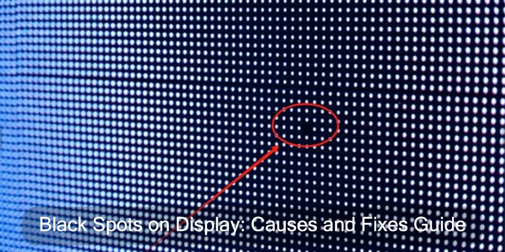
Black spots on display do not always mean dead pixels on direct-view LED systems. One failed LED lamp can create a tiny dark dot, but a loose ribbon cable, failed power supply, or receiving-card problem can turn a complete module or cabinet black. The shape of the fault is usually the quickest way to tell the difference.
This guide is for direct-view LED displays built from modules and cabinets. It covers what black spots look like, why they appear, how to trace the fault, and when a module repair makes more sense than replacing hardware. It does not cover LCD televisions, phones, or computer monitors that use LED backlights.
1. What Are Black Spots on an LED Display?
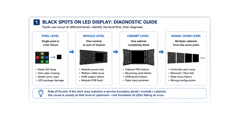
A black spot is a pixel or area that stays dark when the screen should be showing an image. It may be one missing color inside a pixel, a completely dead RGB pixel, a straight line, one module, or a group of cabinets.
That distinction matters. LED display black spots describe what the viewer sees; they are not yet a diagnosis. Before ordering a replacement module, note the size of the dark area, whether it follows a module boundary, and whether it changes on red, green, blue, and white test screens.
1.1 What Does a Black Spot Look Like?
- One dark dot: usually an LED package, die, pad, or solder-joint fault.
- One color missing from a pixel: often one failed red, green, or blue channel.
- A straight dark row or column: points toward the driver IC, scan circuit, or a related PCB trace.
- A clean rectangular block: often matches one LED module and suggests missing power, missing data, or an internal module fault.
- A cabinet-sized area: raises suspicion around the cabinet PSU, receiving card, HUB board, or data input.
- Several cabinets black from the same point onward: commonly follows a controller port, network/fiber link, or daisy-chain failure.
- A mark visible while the screen is off: may be dirt, a damaged mask, impact, or encapsulation damage rather than an electrical blackout.
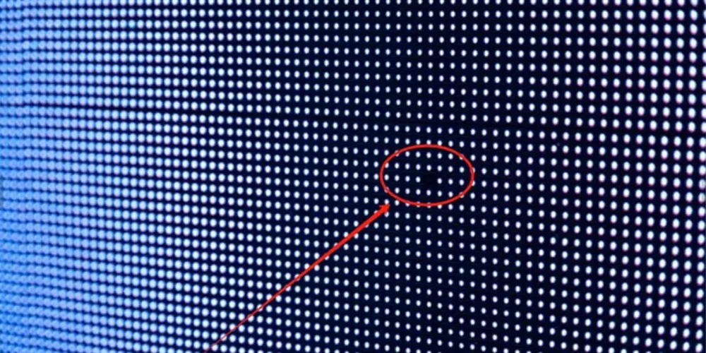
A practical field rule is to compare the dark boundary with the service boundaries. If the area matches one module perfectly, hundreds of LEDs probably did not fail at once; the module has more likely lost power or data.
1.2 Black Spots vs. Dead Pixels
A dead pixel produces no light when it is commanded on. Black spots on LED screen panels are a broader symptom. It may be a single dead pixel, but it may also contain many healthy pixels that are not receiving power or image data.
Separate RGB test screens make the difference clear. If a pixel works on red and green but not blue, only the blue channel has failed. If an entire module remains dark on every pattern, start with its power and data connections instead of replacing individual lamps.
Avoid the familiar advice to press or massage the screen. That comes from LCD troubleshooting. On a direct-view LED module, pressure can crack a package, damage the mask, or lift a solder pad.
1.3 Are Black Spots Serious?
One isolated pixel is usually a visual defect, not a sign that the wall is about to fail. It can still be unacceptable on a fine-pitch control-room wall, broadcast set, or close-view retail display.
The fault deserves prompt attention when a complete module switches off, the area grows after warm-up, several cabinets share the same boundary, or connectors show heat, corrosion, or water marks. These symptoms point to a shared electrical or environmental problem rather than a single lamp.
A dead LED does not spread from pixel to pixel. Moisture, poor power, excessive heat, or repeated solder faults can, however, create additional failures over time.
2. What Causes Black Spots on LED Displays?
Every black area can be traced to one of three paths: the LEDs are not producing light, the module is not receiving stable power, or the module is not receiving valid data.
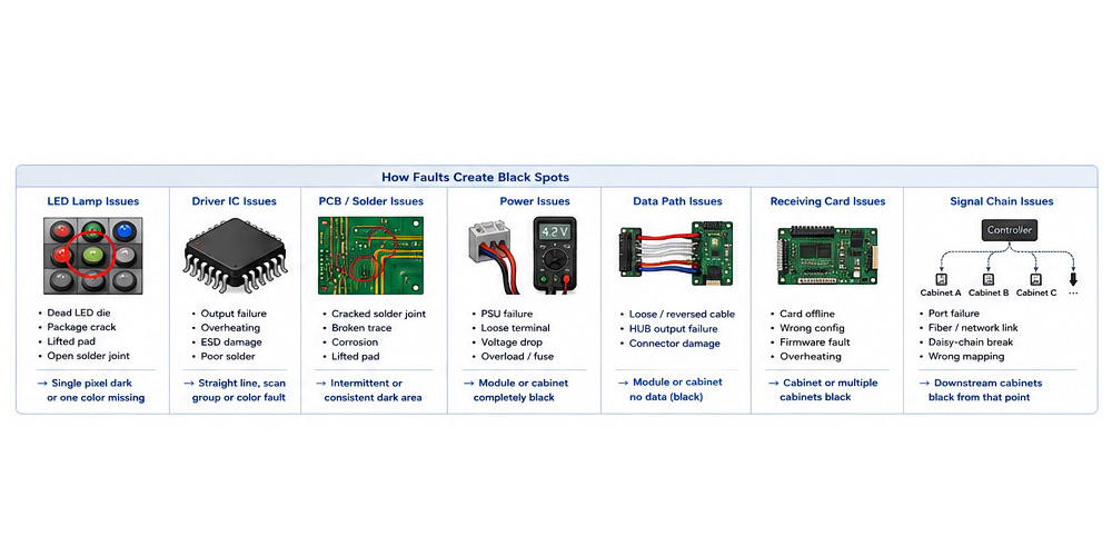
2.1 Dead or Damaged LED Lamps
An SMD pixel package normally contains red, green, and blue light-emitting elements. An internal bond failure, damaged die, cracked package, lifted PCB pad, or open solder joint can disable the whole pixel or one color.
Impact damage is common on rental panels and exposed fine-pitch modules. Cabinet edges and corners are especially vulnerable during handling. If the module is conventional SMD and the pads are intact, a trained technician may replace the lamp. COB and heavily encapsulated GOB modules usually need a manufacturer-approved repair process.
2.2 Driver IC Failure
Driver ICs supply current to groups of LEDs, while scan and decoder circuits select the active rows. A failed output or missing address, clock, latch, or output-enable signal can create a straight row, column, repeated scan group, or missing color channel.
This electrical geometry is the clue. A regular line across many pixels is more likely to be a driver or PCB issue than a row of unrelated dead lamps.
2.3 Power Supply Problems
A failed PSU, loose terminal, oxidized plug, damaged cable, blown protection device, or overloaded branch can make a module or cabinet go black. Power problems often become worse at high brightness because current demand rises.
Do not assume every module runs at 5 V. Many conventional products do, but common-cathode, energy-saving, MiniLED, and manufacturer-specific designs may use other or multiple rails. The module and cabinet documentation is the authority.
Voltage must be checked at the load under the condition that produces the fault. A supply can look normal with no load while a poor connector or long cable causes the module voltage to fall on a white test screen.
2.4 PCB or Soldering Issues
The module PCB carries power and control signals between the connectors, driver ICs, and LEDs. Cracked joints, lifted pads, broken traces, corrosion, board flex, and poor earlier rework can interrupt those paths.
Intermittent faults that appear with heat or vibration often come from this group. If light pressure changes the symptom, that is evidence of a weak connection, not a repair method.
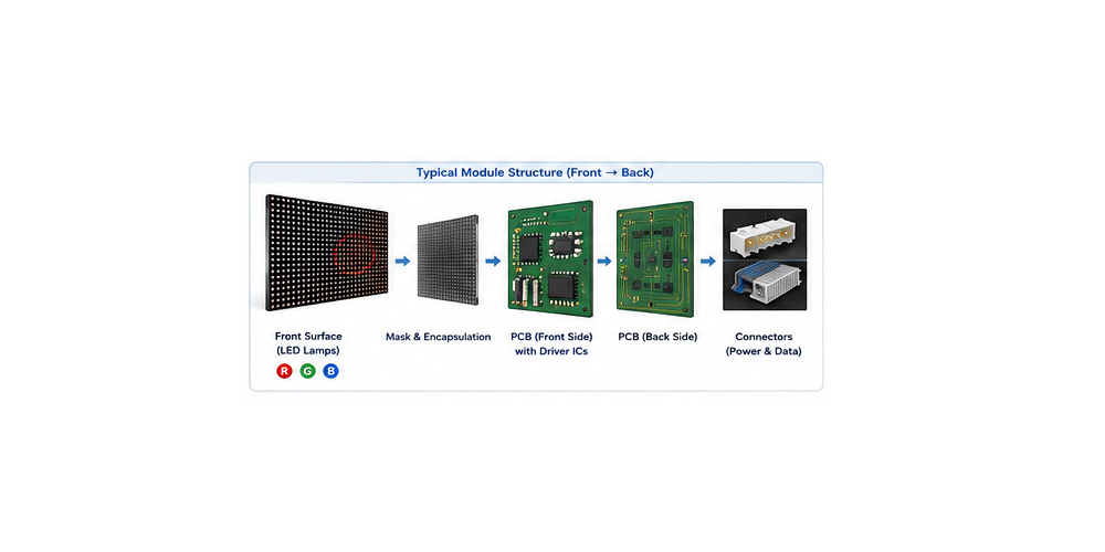
2.5 Data Cable or Receiving Card Problems
The receiving card sends module data through a HUB or adapter board. A loose or reversed ribbon cable, damaged board-to-board connector, failed HUB output, offline receiving card, wrong receiver configuration, or broken network link can black out a module or cabinet.
Control software can help. The official NovaStar NovaLCT manual documents screen configuration and monitoring functions. Available voltage, temperature, and communication data depend on the installed receiving card and peripherals, so check the manual for the exact hardware.
2.6 Physical Damage and Environmental Factors
Impact can break packages or PCB pads. Moisture and condensation corrode connectors and may create leakage or short circuits. Blocked airflow raises cabinet temperature. Dust, salt, and corrosive pollutants make connection problems worse, while unapproved cleaning chemicals can damage masks, coatings, and encapsulation.
If the mark is visible with power off, inspect the surface under side lighting before opening the cabinet. The fault may be optical rather than electrical.
3. How to Diagnose Black Spots on an LED Display?
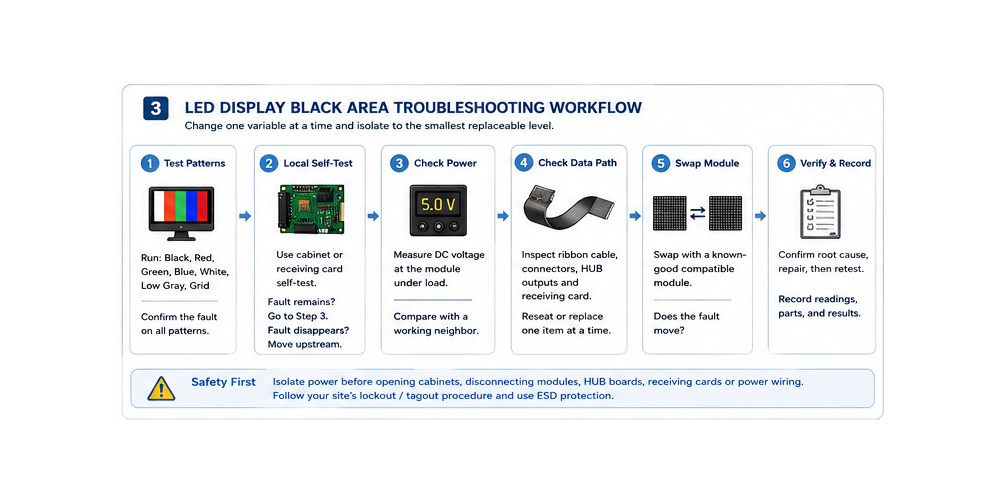
A disciplined LED display troubleshooting process narrows the fault to the smallest replaceable level: pixel, module, cabinet, power branch, or signal chain. Photograph the original condition and label the affected position before moving anything.
Safety: Isolate power before disconnecting modules, HUB boards, receiving cards, or power wiring. Commercial work should follow the site’s energy-control procedure; OSHA’s lockout/tagout guidance explains the risk of unexpected energization during service. Handle bare electronics using the ESD controls required by the manufacturer. Live AC work, wet equipment, and burned connectors belong with qualified personnel.
3.1 Check With Test Patterns
Run black, red, green, blue, white, low-gray, and grid/crosshatch patterns. RGB screens isolate individual color channels. White loads all channels and can expose a weak power branch. Low gray reveals weak pixels, flicker, and calibration mismatch. A grid makes module boundaries and mapping errors obvious.
Use the cabinet or receiving card’s local self-test when available. If the fault remains during that test, it is in or after the cabinet control hardware. If the local test is clean but normal video is not, move upstream to the processor, source, scaling, mapping, or signal transport.
3.2 Check Whether the Problem Moves With the Module
With power isolated, swap the suspect module with a known-good compatible module. It must match the product, scan mode, orientation, and electrical design; using a spare from the same batch also reduces color differences.
- The fault moves with the module: repair or replace that module.
- The fault stays in the original position: check the ribbon cable, HUB output, receiving-card configuration, and local power feed.
Change one item at a time. Swapping the module, cable, card, and PSU together may restore the picture, but it also destroys the evidence that tells you which part failed.
3.3 Inspect Power and Data Connections
After isolating power, check for loose or reversed ribbon cables, damaged pins, partially inserted connectors, overheated terminals, corrosion, water residue, and strained wiring.
Where the manufacturer’s service procedure permits measurement, compare the affected module or cabinet with a working neighbor. Measure the specified DC rail at the module under load, not only at the PSU. Never raise the output voltage beyond specification to hide cable or connector loss.
3.4 Test the Receiving Card and Signal Path
Back up the working receiver configuration before sending parameters or replacing a card. Confirm that the expected receiving cards are online, the controller port mapping is correct, and the receiver-to-HUB connection is secure. Review communication, temperature, voltage, and error data where the hardware supports it.
If cabinets A and B work but C and everything after C is black, test the link into C and the output from B first. An approved bypass or known-good cable can prove the first failed link without disturbing the rest of the wall.
| Symptom | Likely Cause | First Check | Usual Fix |
|---|---|---|---|
| One pixel stays black on RGBW | LED package, pad, or solder joint | Inspect on separate color screens | Lamp repair or module replacement |
| One color is missing | LED channel, driver output, or joint | Compare red, green, and blue patterns | Component repair or module replacement |
| Straight row or column is dark | Driver, decoder, or scan signal | Move the module and inspect the pattern | PCB repair or module replacement |
| One module is black | Power, ribbon cable, HUB output, or PCB | Measure at the module; swap one item | Repair input path or replace module |
| One cabinet is black | PSU, receiver, HUB, input, or mapping | Check indicators, local test, and inputs | Repair the failed assembly |
| Several cabinets fail downstream | Controller port or data-chain link | Bypass the first failed link | Replace link hardware or correct mapping |
4. How to Fix Black Spots on an LED Display?
When deciding how to fix black spots on LED display systems, repair only the level that the tests have proved faulty. The modular construction of an LED wall normally allows lamp, cable, board, PSU, card, or module service without replacing the complete display.
4.1 Replace the Damaged LED Module
LED module replacement is the sensible field fix when several pixels have failed, PCB pads are damaged, corrosion is widespread, the surface is cracked, or the module has a confirmed internal circuit fault.
The spare must match physical size, pixel pitch, resolution, scan mode, connector orientation, and electrical specification. LED type, production batch, and calibration also affect how well the replacement blends with the wall.
Label power and data cables before removal. After installation, run the same test patterns used during diagnosis. If the black area stays at the original position with a good replacement module, the module was not the cause; return to the cable, HUB, and power path.
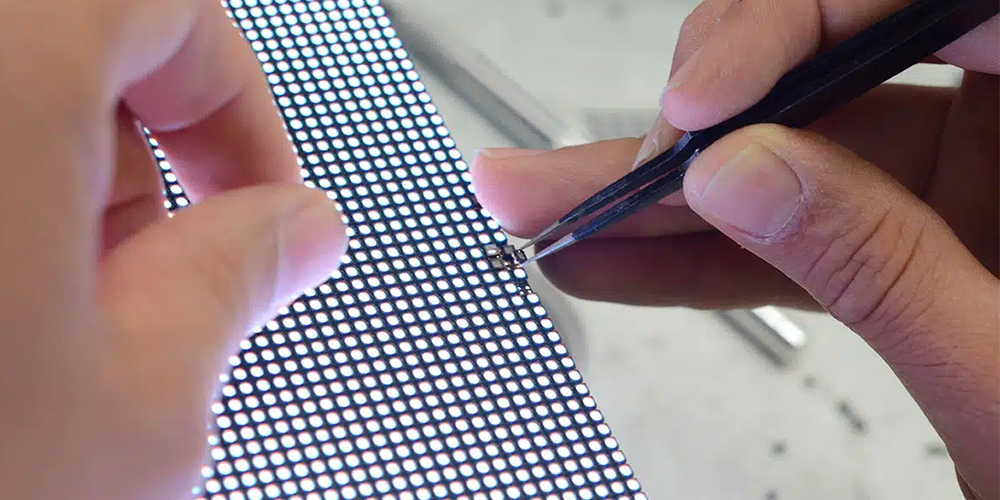
4.2 Repair or Replace the LED Lamp
One or two failed SMD lamps can be economical to repair on a properly equipped bench. The technician needs the correct package, orientation, and rework profile, and must confirm that the pads have not lifted.
Choose module replacement instead when many lamps are affected, the PCB is burned, the matching LED bin is unavailable, or the module uses a COB/GOB construction that is not suitable for ordinary field rework.
4.3 Check the Driver IC and PCB
For a confirmed line, scan-group, or repeated color fault, inspect the driver and logic path. A repair bench may check local rails, signal continuity, driver outputs, decoder or buffer components, connectors, solder joints, and damaged traces.
Replace only a confirmed component. Heating every IC or reflowing the board without a diagnosis can lift pads and turn a stable fault into an intermittent one.
4.4 Fix Power and Signal Problems
Reseat or replace a proven faulty data cable. Repair loose, oxidized, or overheated power connections. Replace a failed PSU only with an approved equivalent that matches voltage, capacity, protection, cooling, connectors, and grounding. Restore receiver settings from a verified backup, and repair the first failed link in the controller chain.
Do not hot-plug modules or control cards unless the manufacturer provides a supported hot-swap procedure.
4.5 Recalibrate After Repair
A replacement module may work perfectly and still look brighter or warmer than its neighbors. LED batch, operating age, and calibration data all affect the match.
Apply the manufacturer’s calibration workflow, then run RGBW, low-gray, gradient, and grid patterns at normal viewing distance. Test at representative low and high brightness and allow the wall to reach a stable temperature. A practical field soak is often 30-60 minutes, unless the manufacturer specifies another acceptance test.
Record the failed position, root cause, part number, readings, configuration version, and final test result. That record is useful when the same cabinet returns with another fault months later.
5. Should You Repair or Replace the LED Display?
Most black-spot faults do not justify replacing the full LED display. The decision depends on the size of the failure, how often it returns, the condition of the rest of the wall, and whether compatible spares are still available.
| Situation | Recommended Action | Why |
|---|---|---|
| One or two black pixels | Monitor if acceptable, or repair during planned service | The fault is local and may not affect normal viewing |
| Several dead pixels on one module | Replace or bench-repair the module | A single module repair is faster than repeated lamp work |
| One whole module is black | Check power, ribbon cable, and HUB output first | A healthy module can look dead when its input is missing |
| Several modules or one cabinet are black | Test shared power, receiver, HUB, and signal path | The modules may all be healthy |
| Black spots keep appearing across cabinets | Inspect the full system and environment | Repeated faults suggest heat, moisture, power, or aging |
| The display is old and spares are scarce | Compare continued repair with an upgrade | Access and obsolete parts may cost more than the repair |
For an upgrade decision, ask the service provider to separate access labor, diagnosis, component repair, modules, receiving cards, PSUs, calibration, commissioning, and warranty. A single total price makes it difficult to compare a targeted repair with a replacement project.
6. How to Prevent Black Spots on LED Displays?
6.1 Stable Power
Use the specified PSUs and protection devices, size branches for the expected load, and keep high-current terminals secure at the manufacturer’s torque. Inspect plugs and distribution points for heat discoloration and voltage drop. Stable grounding and appropriate surge protection are part of the installation, not optional extras.
6.2 Moisture and Impact Protection
Maintain cabinet seals, cable glands, drainage, and ventilation. Investigate condensation or water marks before corrosion reaches multiple connectors. For rental and front-service screens, use the correct module tools and protective packaging; fine-pitch LEDs can be damaged by clothing, cables, and careless cleaning.
6.3 Regular Maintenance
Run RGBW, low-gray, and grid patterns on a schedule rather than waiting for a customer to notice a fault. Check airflow, fans, filters, power and data connections, communication errors, and any available temperature or voltage trends. Keep current backups of controller mapping, receiver settings, and calibration.
6.4 Spare Modules
Store matched modules in a dry, ESD-controlled area and label them by product, batch, scan mode, and calibration status. Keep a small set of approved data cables, receiving cards, HUB boards, and PSUs as well. A spare module does not help when the cabinet has lost its shared power or signal path.
7. FAQ
7.1 What causes black spots on an LED display?
Common causes include a failed LED lamp, cracked solder joint, damaged PCB trace, driver IC fault, missing module power, loose data cable, failed HUB output or receiving card, controller-link problem, impact, heat, moisture, and corrosion. The shape of the dark area usually points to the correct level.
7.2 Can black spots on an LED screen be fixed?
Yes. Depending on the diagnosis, the fix may be lamp replacement, PCB repair, a new data cable, a corrected power connection, a replacement receiving card or PSU, or one replacement LED module.
7.3 Are black spots the same as dead pixels?
No. A dead pixel is one pixel that emits no light. A black spot is the visible symptom and can include many working pixels that have lost power or data.
7.4 Can I replace only one LED module?
Usually. The replacement must match the display’s pitch, dimensions, resolution, scan mode, electrical design, connectors, and orientation. Calibration may be needed to match brightness and color.
7.5 Why is one LED module completely black?
The usual causes are missing DC power, a loose or damaged ribbon cable, a failed HUB output, or a module PCB fault. Measure the module input under load and change one known-good part at a time.
7.6 Will black spots spread?
A dead LED does not spread. More spots can appear if the underlying cause affects several components, as happens with moisture, overheating, unstable power, corrosion, or repeated solder problems.
8. Conclusion
Start with the shape of the black area. One dark pixel points toward the LED package; a line points toward the driver or scan circuit; a module-sized rectangle points toward local power, data, or the module PCB; and a cabinet or downstream fault points toward shared power and signal hardware.
Run test patterns, back up the configuration, and change one part at a time. Once the failed level is proven, most repairs are limited to a lamp, cable, board, PSU, receiving card, or LED module. Replacing the whole display is the last option, not the first.
For a useful service quotation, send the display model, pixel pitch, controller and receiving-card model, photos of RGBW test screens, the affected module or cabinet position, and a note on whether the fault changes with brightness or warm-up.