

A Colorlight controller upgrade should start with a verified record of the working system, a model-specific compatibility check, and a tested recovery route. A larger pixel rating or a newer software installer does not establish that the existing receiving cards, cabinet parameters, optical links, and operating presets will work together after the change.
This guide is for AV integrators evaluating an installed wall before expanding it or replacing its processor. It separates the purchasing decision from the maintenance-window procedure. The proposed checks are a planning framework, not instructions to flash an unidentified device or alter a live show system.
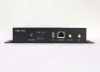
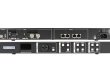
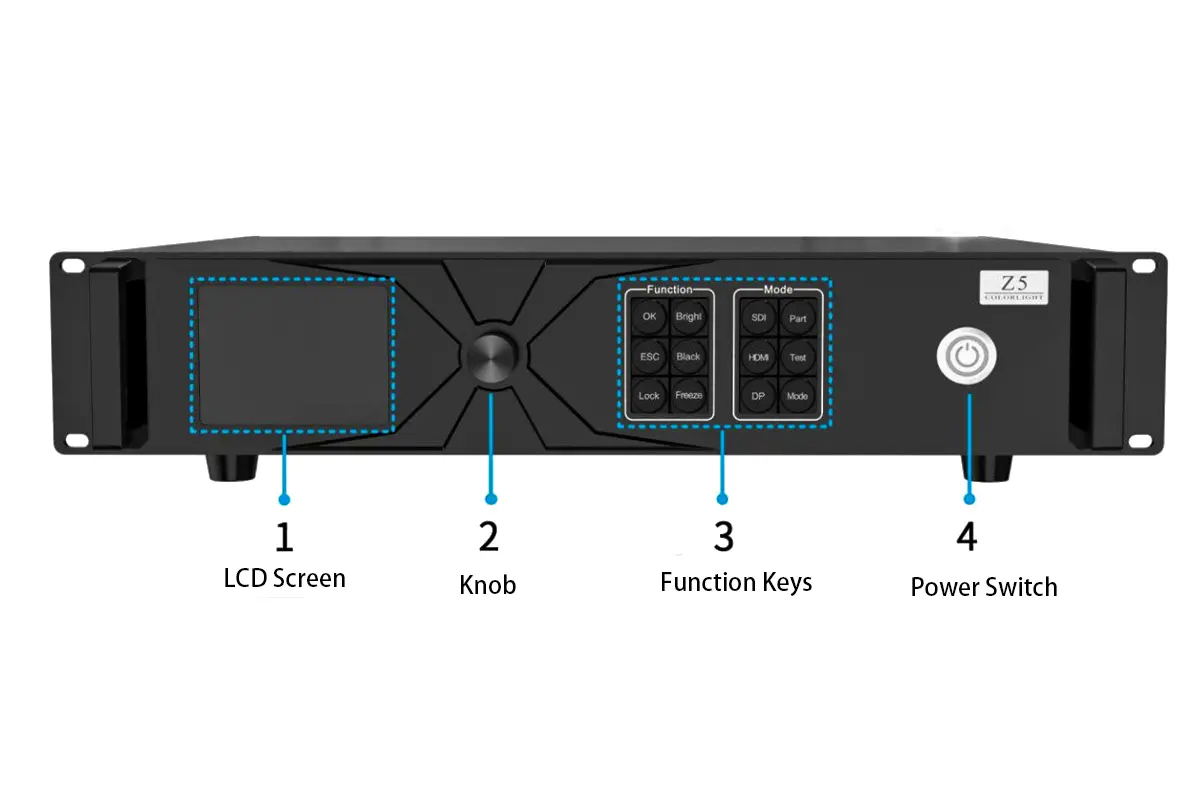
The software examples below were checked against Colorlight’s published release notes on October 21, 2026. X8m and Z5 images illustrate different hardware interfaces; they do not establish that either model is a direct replacement for the other.
1. Define What the Colorlight Controller Upgrade Must Change
Write the required result as an observable change. Examples include adding cabinet columns, accepting a different source format, replacing an unsupported processor, or making a particular backup path available. Keep the requirements separate: adding input resolution does not necessarily require more display pixels, while extending the physical wall does.
For each requirement, identify the current limitation and the evidence that the proposed Colorlight controller resolves it. If the complaint is intermittent video loss, first determine whether the problem is upstream of the processor, in the output path, or inside a cabinet. Replacing the central device without identifying the fault can preserve the original problem while introducing new variables.
Separate mandatory functions from convenient additions. A venue may need the existing presentation workflow to continue unchanged but only want a future camera feature. Put the first in the acceptance criteria and the second in a priced option. This gives the buyer a reason to reject an unsuitable substitution even when its headline specification looks stronger.

2. Capture the Working System Before Comparing Hardware
The useful baseline is the installed configuration, including exceptions. Photograph labels and record the Colorlight controller model, hardware revision where available, firmware, input boards, output boards, and normal operating mode. An old purchase order is supporting evidence, but it may predate a repair or field substitution.
01. Inventory the downstream chain
List receiving-card models and revisions by cabinet group, plus optical converters and their operating modes. Record cabinet pixel dimensions, receiver count per cabinet, data order, cable identifiers, and the output port serving each chain. Distinguish a spare cabinet from an active cabinet so the drawing does not silently overstate the installed count.
Record differences instead of averaging them away. A replacement module installed last year may use different drive components or require different parameters. A successful test with one original cabinet cannot establish compatibility for that repaired group. The Colorlight controller evaluation should include every materially different configuration that will remain in service.
02. Preserve files and operating evidence
Keep the working project, receiver parameters, applicable calibration data, source presets, and the installer used to open them. Store an untouched copy separately from the trial copy. Record how each file was obtained and which device or cabinet group it belongs to. A folder called “latest” offers little protection when two technicians have different versions.
Capture normal source selection, displayed test patterns, brightness settings, and any automation commands before changing the Colorlight controller. These observations provide a comparison point if an upgrade produces a subtle color or scaling difference. Photographs support the record, but measured requirements need suitable measurement equipment and an agreed method.
| Decision | Evidence to obtain | Who should resolve a gap |
|---|---|---|
| Retain existing receivers | Exact models, revisions, firmware and supported feature combinations | Controller supplier with cabinet manufacturer |
| Reuse current cabling | Port map, converter models, link mode and installation condition | Integrator responsible for the installed route |
| Preserve the show workflow | Required inputs, presets, switching behavior and automation sequence | Venue operator and show-control integrator |
| Meet the downtime limit | Trial results, restoration procedure and reserved recovery time | Commissioning lead with venue management |
| Accept the commercial scope | Included hardware, testing, support and exclusions | Buyer and proposed service provider |
3. Verify Software Support and Receiver Features Separately
Check the software branch for the exact Colorlight controller and operating system. Colorlight’s English iSet release notes list X8m and X12m support under V6.2, while the V7.0 Windows notes explicitly list removal of that support. The lesson is specific: a higher version number is not evidence that an existing processor remains supported.
The language editions of release notes may differ. If the relevant package description, manual, or regional page gives inconsistent guidance, obtain written clarification for the actual package before scheduling the change. Do not infer a supported combination from a download being available or from a model appearing somewhere else in the catalogue.
Use the Colorlight software and document archive to identify resources, then verify the applicable current release with the manufacturer. PC configuration software, device firmware, and cabinet parameter files serve different purposes. Installing a PC application does not itself prove that a Colorlight controller has suitable firmware.
01. Turn “compatible” into a feature-specific answer
Ask whether the proposed combination supports ordinary picture output and each required advanced function. These are separate questions. For example, Colorlight’s Z8t Specification V2.1 recommends i10/K10 receiving cards and warns that some functions may be unavailable with i9+/K9+/i9. That statement concerns the documented Z8t combination; it is not a universal rule for all processors.
Request the relevant firmware and receiver requirements alongside any claimed function. If a supplier only confirms that a picture appears, the answer does not establish the requested synchronization, color-processing, monitoring, or redundancy behavior. The Colorlight controller shortlist should show unresolved functions explicitly rather than treating them as included.
For remote review, give the support engineer a compact equipment schedule rather than a photograph of the front panel alone. A Colorlight controller question is easier to resolve when the requested behavior, current versions, proposed versions and affected receiver groups appear together. Record the response date and the exact configuration it approves.
4. Recalculate the Output Layout Under the Required Conditions
Evaluate total pixels, dimensions, individual output loads, and receiver limits together. The Colorlight controller must support the intended combination of frame rate, color depth, layout, and operating mode. A maximum total-pixel figure alone cannot establish that a particularly wide canvas or an unevenly loaded port arrangement is valid.
Start with the physical cabinet raster. In a hypothetical planning example, twelve columns by six rows of cabinets, each containing 192 by 192 pixels, form a 2304 by 1152 canvas: 2,654,208 pixels. This calculation describes the wall only. It does not select a processor or prove any model’s port capacity.
If the example wall is distributed over six equal output chains, each chain carries twelve cabinets, or 442,368 pixels. Real cable routes may produce unequal chains, so calculate each actual route. Compare those loads with the chosen model’s published limits at the intended settings; do not transfer a capacity quoted for another frame rate.
For a Colorlight controller expansion, reserve the proposed additional cabinets in the drawing now. A purchase that meets today’s total load can still fail the intended expansion if the added section overloads one route or exceeds a dimension limit. Ask for an output map attached to the quotation, with any required recabling shown.
Identify temporary arrangements as well. If the venue occasionally divides the wall into two displays, ask whether the proposed Colorlight controller preserves that configuration and its presets. A quote checked only against the largest combined canvas can miss the source-routing requirements of the smaller event layout.

Keep source resolution separate from native wall resolution. Review cropping, scaling, aspect ratio, and the required readable content. A processor accepting a large input cannot create missing physical pixels in the wall. The X8m specifications and input guide provides a model-specific example of why input and output limits need separate checks.
Also distinguish alternative outputs from additional capacity. The Z5 setup guide discusses its Ethernet and fiber connections; a fiber connector must not be counted as extra independent screen capacity without confirmation of the documented output relationship. Require the converter and receiver chain to be identified by model.

5. Test a Representative Chain Before the Venue Cutover
A useful trial includes the proposed Colorlight controller, the intended software and firmware, a representative receiver chain, and the actual source workflow. Testing an unrelated demonstration wall may prove that the device works, but it cannot settle compatibility with the retained installation.
Agree on the trial’s boundaries in writing. Include each receiver variant, the required source formats, normal presets, and any claimed backup behavior. Where a full-length route cannot be reproduced, mark that limitation and schedule an on-site test. A short bench cable should not stand in for an untested optical route or installed connection.
Use test content that exposes different defects: cabinet identifiers for mapping, fine text for scaling, neutral gray and low-level gradients for uniformity, motion for cadence, and the venue’s real presentations for operating fit. Do not describe a Colorlight controller as camera-ready solely because a still photograph looks clean; use the intended camera configuration when camera capture is part of acceptance.
Record results against an unchanged baseline. If a preset works only after a manual adjustment, document that adjustment and repeat the sequence from the saved state. The purpose is to establish reproducible operation, not to assemble a successful demonstration through undocumented corrections.
Include the normal control computer in the trial. A Colorlight controller can behave correctly from its front panel while the venue laptop has a different software branch, operating system or connection configuration. Test the actual operating method and record which computer configuration belongs in the approved service package.
| Test | Expected result to agree | If it fails, capture |
|---|---|---|
| Mapping and cabinet order | Every identifier appears in its scheduled position | Port, cabinet index, receiver variant and loaded parameter file |
| Normal source sequence | Required sources and presets produce the agreed layout | Input format, preset name, switching order and symptom |
| Image consistency | Reference content meets the agreed visual or measured criteria | Operating brightness, calibration state and comparison conditions |
| Authorized backup test | The specified failure produces the agreed recovery behavior | Failure point, active path, elapsed recovery and remaining interruption |
| Saved-state restoration | The documented restoration sequence returns normal operation | Files, versions, steps and settings requiring manual intervention |
6. Give Rollback a Deadline, Owner and Tested Route
A rollback plan for a Colorlight controller upgrade should say who makes the decision, what triggers it, and how much time restoration requires. “Keep the old unit nearby” is incomplete if the receiving-card firmware or cabling has also changed and no longer matches that unit’s saved configuration.
List each changed component and its supported recovery method. Ask the manufacturer whether a firmware downgrade is supported for the exact hardware. Some changes may require a different recovery procedure or a spare device; do not assume that loading an older file is always possible. If restoration cannot be demonstrated, describe the maintenance plan as lacking a verified rollback path.
Set the decision deadline before the venue’s reopening time. For example, a hypothetical four-hour window with a demonstrated ninety-minute restoration and a thirty-minute operating check leaves two hours for the attempted change. Those numbers are an illustration, not a promised installation duration. Use measured trial times for the real Colorlight controller plan.
Assign one person to keep the change record while the commissioning lead performs the approved work. Record the order, device identity, file version, result, and any deviation. Avoid adding an unrelated firmware update during the same window simply because the system is already offline; it expands the recovery problem without advancing the approved requirement.
Physical access belongs in the schedule. Compare chassis depth, supports, ventilation requirements, connector space, power arrangements, and the route for removing the old unit. A Colorlight controller that fits the nominal rack width can still be difficult to service if cables or adjacent equipment block access.

7. Accept the Saved Configuration and the Operator Workflow
Accept the Colorlight controller installation against the agreed test record, not just an illuminated wall. Confirm the final hardware identities, software and firmware versions, output map, required source behavior, and any feature limitations. Mark failed or untested requirements separately from those that passed.
Have the venue operator run the normal start, source selection, presentation, and shutdown sequence under the approved procedure. The integrator may know how to recover a hidden input setting, while the daily operator does not. Capture the necessary instructions in the handover package and repeat the sequence without coaching before closing that acceptance item.
Archive the final project alongside the original baseline, clearly labeled as different states. Record which Colorlight controller is installed, which device is retained as a spare, and whether that spare was tested with the final receiving system. Include the support contact and the information required to report a fault without sending an entire uncontrolled configuration folder.
Keep commercial exclusions visible: overnight labor, new optical converters, receiver replacement, recabling, recalibration, or a second attendance may fall outside a processor-only quotation. Resolving those items before purchase helps prevent a technically suitable Colorlight controller from becoming an incomplete upgrade project.
Finally, agree who owns follow-up faults after the first event. Separate a Colorlight controller fault from an upstream source issue or an unrelated cabinet repair, while retaining one contact responsible for coordinating diagnosis. The handover should explain how the operator reports the symptom, preserves the current state and obtains the next approved action.
Frequently Asked Questions
Can two supported software versions share one project file?
Do not assume they can edit and save it interchangeably. Preserve the original file and test a copy with the proposed release. If the application converts the project, keep the converted copy separate and obtain the supported route for returning to the commissioned version.
Does a detected receiving card prove all requested features work?
No. Detection establishes communication under the observed conditions. Feature support and acceptable picture output still need model-specific confirmation and tests. Record the card revision and firmware, especially when a wall contains more than one receiver variant.
Should every device be updated to the newest firmware together?
Only make the changes required by a documented, supported upgrade path. Coordinated updates may be necessary for some combinations, but an indiscriminate update adds variables. Obtain the required sequence and recovery instructions before the maintenance window.
Can the old Colorlight controller become the backup?
Possibly, but retention alone does not make it a working backup. Verify the final receiver compatibility, load, input requirements and supported failover arrangement. Test the exact failure scenario the venue expects the backup to handle.
What if a supplier cannot confirm an undocumented receiver revision?
Keep that compatibility item open. Request identification assistance from the cabinet manufacturer and provide clear labels and existing records. Consider a representative sample assessment or a separately priced receiver replacement scope; do not approve the full installation on an assumed match.
Prepare an Upgrade Inquiry With the Existing System Record
Send the installed model list, cabinet raster, port map, working software versions, required changes, and available downtime. Include the functions that must remain unchanged and any receiver groups that differ from the original installation. These details let a supplier distinguish a straightforward processor change from a wider system migration.
For help defining the Colorlight controller and display-system scope, contact EagerLED with your existing configuration and upgrade requirements. Request a written compatibility response, itemized inclusions, and an acceptance plan before committing the venue to a cutover date.