

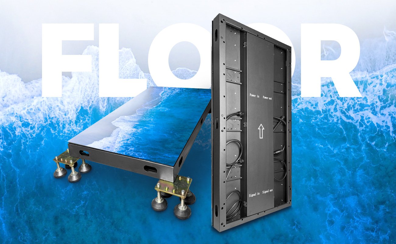
An indoor floor LED display is a modular video screen engineered for horizontal, walkable installation. Unlike a conventional LED wall placed flat, it combines a reinforced surface, load-bearing cabinets, LED modules, a support structure, video processing, and optional sensors. The system converts a video source into synchronized images across the floor while its mechanical structure transfers foot traffic and equipment loads away from sensitive electronic components.
Interactive versions add sensors and a media server. When a person steps on a tile, the sensor reports the position to the software, which renders a response such as ripples, particles, or a changing path and sends the updated frames back to the LED controller.
Key Takeaways
- A floor LED screen is a complete structural and electronic system, not a standard LED wall installed horizontally.
- Its main layers are the protective mask, LED module, cabinet, support structure, power and data network, controller, and optional interaction system.
- Pixel pitch controls image detail; load test data and surface design determine whether the system is suitable for walking or equipment.
- An IP rating describes enclosure protection against solids and water. It does not prove slip resistance or structural capacity.
- Front-service access and accurate leveling reduce downtime and help prevent visible seams and trip points.
What Is an Indoor Floor LED Display?
An indoor floor LED display is a full-color direct-view LED system designed to form a level video surface that people can walk on. Individual cabinets lock together to create a larger canvas. Each cabinet contains LED modules, receiving electronics, power components, and a structural frame. A controller divides the source image among the cabinets so the complete floor behaves as one display.
The defining difference is mechanical. A wall-mounted LED panel mainly supports its own weight. A floor system must also manage distributed loads, concentrated loads, repeated impacts, vibration, surface wear, cable protection, and the transition between the display and the surrounding floor.
The Seven Main Parts of an LED Floor System
| System layer | Function | What to verify |
|---|---|---|
| Protective mask | Provides a walkable, wear-resistant viewing surface | Surface texture, replaceability, optical effect, and documented slip testing |
| LED module | Produces the image with red, green, and blue LEDs | Pixel pitch, module resolution, contrast, color consistency, and dead-pixel service process |
| Load-bearing cabinet | Protects electronics and transfers loads to the support system | Cabinet material, distributed- and point-load test methods, locks, and flatness |
| Support structure | Levels the floor and transfers loads to the building or stage | Foot spacing, height adjustment, subfloor capacity, ventilation, and edge transitions |
| Power and data network | Distributes power and image data across the floor | Circuit design, cable routing, redundancy, grounding, and connector protection |
| LED controller | Maps the source image to every cabinet | Total pixel capacity, refresh rate, grayscale, scan mode, and camera compatibility |
| Sensor and media server | Detects users and generates interactive content | Sensor density, latency, calibration, multi-user behavior, and software support |
How the Image Signal Moves Through the Floor
1. A media source creates the content
The source may be a media player, computer, live camera feed, presentation system, or interactive graphics engine. Content should be produced for the floor's native aspect ratio and pixel dimensions. A standard 16:9 video can be cropped or stretched if the physical floor has a different shape.
2. A video processor prepares the signal
The processor scales, crops, switches, and sometimes color-manages the incoming signal. Large floors may be divided into regions so different content can appear in separate areas.
3. The sending system maps pixels to cabinets
The LED control system converts each video frame into data for the receiving cards. The mapping file tells the controller where every cabinet sits in the physical floor. Incorrect mapping can create rotated tiles, broken image sections, or content that jumps at cabinet boundaries.
4. Receiving cards drive the LED modules
Each receiving card sends data to the LED modules in its cabinet. Driver integrated circuits regulate the LEDs to reproduce brightness and color values. Calibration data can compensate for differences between modules and improve uniformity at low brightness.
5. Optional sensors close the interaction loop
In an interactive system, the floor first sends position data back to a media server. The software interprets the input, renders a new visual state, and sends it through the same video-control chain. The audience experiences the complete round trip as a real-time response.
Standard vs. Interactive Indoor LED Floors
| Feature | Standard video floor | Interactive LED floor |
|---|---|---|
| Input | Scheduled or live video | Video plus sensor data |
| Content behavior | Plays a fixed sequence or live source | Changes in response to footsteps or movement |
| Additional hardware | Standard video controller | Sensors, interaction controller, and media server |
| Setup complexity | Lower | Higher because sensor mapping and content logic must be tested |
| Best suited to | Stages, branded floors, weddings, and scenic installations | Museums, retail experiences, games, exhibitions, and experiential events |
| Main risk | Poor mapping or an unsuitable mechanical installation | Added latency, calibration errors, sensor coverage gaps, and software dependency |
Interactivity should be specified as an end-to-end system. A sensor-equipped cabinet alone does not define the user experience. The buyer should also document the number of simultaneous users, the trigger behavior, acceptable response time, content engine, backup mode, and on-site calibration process.
Why Floor Cabinets Need a Different Mechanical Design
The walking surface must spread force across the cabinet while protecting the LEDs below it. The cabinet then transfers that force through its frame and adjustable supports to the subfloor. Panel locks and locating features keep adjacent surfaces level.
Manufacturers usually state a distributed load in kilograms per square meter, but that figure must be read with its test conditions. A high heel, caster, stage leg, or wheel applies force over a much smaller area and can create a more demanding point load. Ask for both distributed- and point-load documentation, the required support spacing, the safety factor, and any restrictions on rolling or dynamic loads.
As a product-specific example, the EagerLED EA-iFloor page states a cabinet size of 500 x 1,000 mm, IP66 protection, front service, and a load capacity above 2,000 kg/m2. These values describe that product page; they are not universal specifications for all indoor LED floors. Review the current datasheet and test documentation before using them in a project specification.
Pixel Pitch, Resolution, and Viewing Geometry
Pixel pitch is the center-to-center distance between adjacent LEDs. A smaller pitch places more pixels in the same area and can show finer detail, but it also increases pixel count, processing demand, and cost.
Floor viewing differs from viewing a wall. People often see the image at an angle, from close range, or through a camera positioned above the floor. Select pitch by testing real content from the actual audience and camera positions rather than relying on one universal viewing-distance rule.
The native pixel dimensions can be estimated as:
- Horizontal pixels = display width in millimeters / pixel pitch in millimeters.
- Vertical pixels = display height in millimeters / pixel pitch in millimeters.
- Total pixels = horizontal pixels x vertical pixels.
The total pixel count affects controller capacity, receiving-card quantity, cabling, content production, and backup design.
Protection Ratings, Slip Resistance, and Indoor Safety
IEC 60529 defines the IP Code used to classify an enclosure's protection against solid objects and water. The two digits describe different types of ingress protection. An IP rating does not state how much weight a cabinet can support, whether the surface is slip resistant, or whether the complete installed floor meets local public-safety requirements.
For an indoor venue, evaluate spilled liquids, cleaning procedures, wet footwear, connector exposure, edge ramps, surface friction, and emergency egress. Ask for the exact IP rating of the top and bottom of the cabinet rather than assuming one number applies equally to every side.
Reference: International Electrotechnical Commission, Ingress Protection ratings.
Installation and Maintenance
An indoor LED floor can be installed on an adjustable support frame, rails, a raised platform, or in a recessed opening. Whichever method is used, the finished surface must remain level and the structure below must support the complete system, people, scenery, and equipment.
Plan the following before installation:
- Confirm the subfloor capacity and approved support spacing.
- Establish the finished height and safe edge transition.
- Route power and data cables away from load points and service paths.
- Provide grounding, circuit protection, ventilation, and access to power and receiving components.
- Assemble and level the cabinet grid before final image calibration.
- Test the floor with the expected content, lighting, users, footwear, and equipment.
Front-service modules allow a technician to remove a module from the display surface without dismantling adjacent cabinets. This can shorten service time, but the maintenance plan must still include safe isolation of power and a method for protecting the surrounding floor during access.
Where Indoor Floor LED Displays Are Used
Indoor LED floors are used for exhibition booths, museums, retail experiences, hotel lobbies, stages, concerts, weddings, clubs, broadcast sets, and brand experience centers. The correct configuration changes by application:
- Touring stages prioritize fast assembly, repeatable leveling, replaceable masks, and durable transport hardware.
- Museums and retail spaces prioritize quiet operation, front maintenance, refined surface appearance, and reliable multi-user interaction.
- Broadcast floors prioritize refresh rate, scan behavior, low-brightness grayscale, color calibration, and control synchronization.
- Entertainment venues prioritize resistance to repeated foot traffic, vibration, spills, and rapid content changes.
For a deeper event-focused comparison, read EagerLED's stage LED screen guide.
Technical Limitations to Plan For
An LED floor is not appropriate for every project. The support platform increases finished-floor height and weight. The walking mask changes contrast and viewing characteristics. Reflections from ceiling lights may be visible. Interactive content adds software, calibration, and support requirements. Fine-pitch systems increase resolution but can also increase component count and cost.
The most reliable design starts with the venue and operating conditions, then selects the mechanical structure, protection, image performance, interaction, and service approach. It does not start with pixel pitch or price alone.
Frequently Asked Questions
Can a normal LED wall panel be used as a floor display?
No. A conventional wall panel is not designed as a walking surface. A purpose-built LED floor requires a reinforced mask, load-bearing cabinet, suitable supports, protected power and data connections, and a level installation designed for the expected traffic.
How does an interactive LED floor detect footsteps?
Sensors in or around the cabinets identify a user's position and send that data to an interaction controller or media server. The software generates a visual response, and the LED controller displays the new frames on the corresponding floor area.
Does a high IP rating make an LED floor safe to walk on?
No. An IP rating addresses enclosure protection against solids and water. Walking safety also depends on structural load tests, surface friction, cabinet flatness, edge transitions, the support system, installation quality, and local regulations.
What is the best pixel pitch for an indoor LED floor?
There is no universal best pitch. The correct choice depends on floor size, viewing and camera distance, content detail, budget, and processor capacity. Compare physical samples using the real content and viewing geometry.
What information is needed to design an indoor LED floor?
Provide the floor dimensions and shape, venue type, installation period, expected traffic and equipment, indoor lighting, viewing and camera positions, content type, interaction requirements, service access, and available power. These inputs are more useful than requesting a price by square meter alone.
Conclusion
An indoor floor LED display works by combining a structurally reinforced walking surface with the same core image chain used by modular LED video systems. Interactive models add a return path from sensors to a real-time content engine. Successful projects depend on the complete system: cabinet and support engineering, surface safety, video control, content, power, data, calibration, and maintenance.
Use the floor LED display buying guide to compare project specifications. For a product-specific design and quotation, review the EagerLED EA-iFloor indoor floor LED display and submit the venue dimensions, application, installation type, pixel-pitch requirement, and interaction needs.