

COB LED technology builds a display by attaching unpackaged LED chips to a circuit substrate and protecting the pixel array with an encapsulating material. In a direct-view screen, individually controlled red, green, and blue emitters create the image. This construction can support fine pixel spacing and a protected display surface, but it does not define the performance of the finished video wall.
For an AV integrator, the useful question is what this construction changes for a particular installation. A screen for spreadsheets, a museum exhibit, and a camera-facing presentation space may need different brightness settings, processing, service access, and acceptance tests—even when all three use COB LED technology.
This guide focuses on indoor LED displays rather than COB lighting strips or spotlights. It explains the packaging choices, benefits, limitations, and purchasing questions that help turn a technology preference into a workable display specification.
1. What Does COB Mean in LED Displays?
COB stands for chip on board. The term describes an assembly approach: the semiconductor dies are attached at board level instead of first being enclosed in separate LED packages. COB LED technology therefore identifies how the emitters are integrated, not a particular resolution, screen size, or brightness rating.
A conventional SMD display uses packaged LEDs soldered onto a module PCB. COB moves the chip attachment and associated encapsulation into the module construction. The finished surface can look continuous, but the image still consists of discrete pixels. It also remains a tiled assembly with physical module and cabinet boundaries.
Three assembly levels matter when reading a quotation:
- Module: the pixel-bearing assembly that a technician may remove for service.
- Cabinet: the supporting assembly that holds modules and associated electronics.
- Video wall: the installed collection of cabinets, processing, power distribution, mounting, and control equipment.
A vendor may use “panel” for either a module or a cabinet. Resolve that terminology before comparing quantities or spare-part prices. COB LED technology does not make parts interchangeable simply because their outer dimensions match; connectors, electronics, calibration, and mechanical interfaces also matter.
COB lighting uses a related assembly concept, often to produce a combined light source. A full-color display must instead control image pixels across a matrix. Lighting specifications such as lumens per fixture do not replace display specifications such as luminance, native resolution, and grayscale behavior.
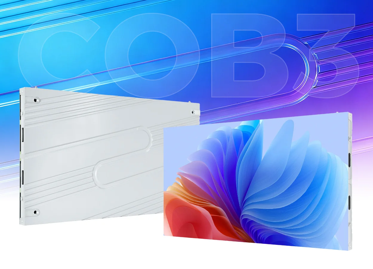
2. How Does COB LED Technology Work?
01. From LED chips to addressable pixels
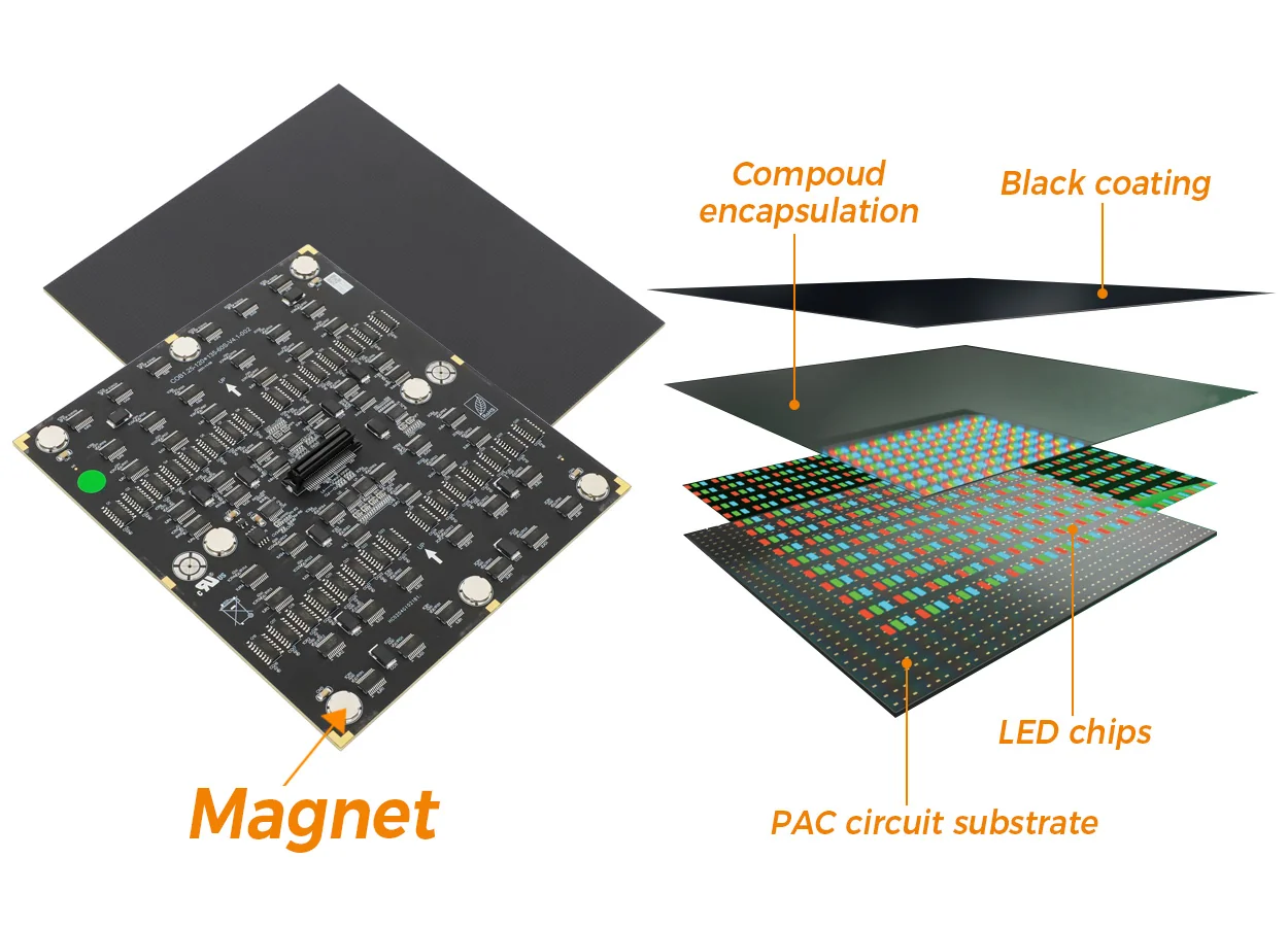
LED dies emit light when driven electrically. Red, green, and blue channels are controlled to form the required pixel colors, while the physical layout establishes the pixel pitch. With COB LED technology, die placement, electrical interconnection, and encapsulation must work together across the module.
Encapsulation protects the emitting assembly and influences its optical surface. Its material, thickness, consistency, and finish can affect reflections and appearance. A photograph of a dark module cannot establish its measured contrast or uniformity under room lighting.
Pixel pitch is the center-to-center distance between adjacent pixels. Reducing pitch increases the available pixel count within a fixed screen area. It does not improve a poor source image, correct inappropriate scaling, or guarantee that small text is readable from the intended seats.
02. From the source signal to visible light
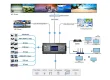
A typical system receives video, maps it to the wall, distributes data through receiving electronics, and drives the emitters. The exact signal route depends on the controller and display architecture. COB LED technology forms the image-producing hardware within that system; it does not replace the video processor or determine every processing function.
Refresh behavior and grayscale depend on the drive configuration as well as the LEDs. Low-level gradients can reveal steps or uneven output that a bright demonstration video conceals. Inspect near-black content at the brightness the customer will actually use.
Calibration helps correct measured brightness and color differences between pixels or modules. Mechanical alignment is a separate requirement: calibration cannot physically straighten a cabinet or close an incorrectly adjusted joint. Both procedures contribute to a wall that appears consistent across its full area.
Assess COB LED technology as part of this complete chain. A convincing sample should use the proposed electronics and settings, with its configuration recorded so that the delivered equipment can be compared fairly.
3. Wire-Bond vs. Flip-Chip COB: What’s the Difference?
COB describes the board-level construction; wire bonding and flip-chip describe different ways of making chip connections. Treating every product using COB LED technology as automatically wire-free hides a meaningful design distinction.
In a wire-bond arrangement, fine bonding wires provide electrical connections between die contacts and surrounding connections. Those wires are protected within the assembly. Their presence alone does not establish that a product is unreliable; material selection, assembly control, and operating conditions affect the result.
Flip-chip construction positions the relevant die contacts toward the substrate and connects them through a suitable bonding process. This removes the corresponding bond wires and can provide a more direct thermal path. It still requires sound attachment interfaces and a board and cabinet capable of moving heat away.
For COB LED technology marketed as “full flip-chip,” ask whether the claim applies to all color channels in the quoted module. Obtain the construction description for that module revision rather than relying on a family brochure.
The purchasing distinction is practical. Compare documented construction, operation at the required brightness, and support arrangements. Neither a wire-bond label nor a flip-chip label provides a complete prediction of failure rate or lifetime. A well-supported product with demonstrated performance is more useful than an unexplained packaging superlative.
Ask the supplier to identify the evidence behind any thermal or reliability comparison, including the configurations and test conditions. A claimed improvement between two laboratory samples should not become a guaranteed saving for every installed wall.
4. Key Benefits of COB LED Displays
01. Fine-pitch layouts for demanding visual content
Removing separate lamp housings gives designers another route to dense pixel arrays. This is a useful reason to consider COB LED technology when viewers need to inspect detailed diagrams, fine labels, or multiple information windows within a limited wall area.
The benefit comes from the selected pixel matrix, not the name alone. At the same active dimensions and actual pitch, two displays have comparable geometric pixel counts even if their packaging differs. Optical performance and processing can still make their images look different.
02. Protection around the emitting surface
Encapsulation can reduce direct exposure of delicate emitters during handling and routine use. For installations near people, that may simplify surface care compared with an exposed-lamp construction. COB LED technology is nevertheless not an impact-proof material or permission to use any cleaning chemical.
Request the approved handling and cleaning procedure. Protection is useful when it survives the contact, contamination, and maintenance conditions of the intended installation—not simply when a demonstration shows water or pressure applied to an unidentified sample.
03. A surface that can support better ambient-light performance
A suitably engineered dark surface can reduce reflected room light and help preserve perceived black levels. Surface finish matters alongside LED output. Compare samples with the room lights on and from side seats, because reflections can change with viewing geometry.
Use the following checks to make claimed benefits of COB LED technology observable. Agree acceptable results before evaluating competing samples.
| Claim | What to demonstrate | What to record |
|---|---|---|
| Readable fine detail | Actual drawings or spreadsheets at the intended scale | Pixel matrix, source scaling, and viewing positions |
| Consistent dark images | Near-black ramps and gray fields at operating brightness | Visible steps, color tint, and module boundaries |
| Controlled reflections | Black content under representative room lighting | Light positions, viewing angles, and surface reflections |
| Practical surface care | The manufacturer-approved cleaning procedure | Permitted materials, pressure limits, and access needs |
COB LED technology can also support efficient thermal designs, particularly with suitable chip attachment. However, packaging alone cannot establish lower system electricity use. Compare measured input power at matched luminance, content, white point, and operating conditions.
5. Drawbacks and Limitations of COB LED Technology
01. Purchase price and service arrangements need context
A finer-pitch proposal may require more demanding production, inspection, and calibration. The resulting purchase price depends on the actual configuration and commercial scope. COB LED technology has no universal price premium that can be applied to every SMD alternative.
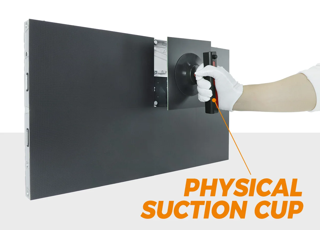
Repair also needs two separate questions: how the installation returns to service, and how a defective component is repaired afterward. An installer may exchange a module on site while the manufacturer evaluates the removed module for specialized repair. The available process depends on the design and service policy.
Do not assume that every damaged pixel is economically repairable, or that all COB pixels are permanently unrepairable. Obtain the return procedure, warranty exclusions, repair charges, and replacement policy. Matching spare modules can reduce downtime, but they require suitable storage and identification.
02. Encapsulation has optical and mechanical trade-offs
The protective layer introduces its own quality requirements. Differences in surface finish, damage, or replacement-module appearance can become visible under certain lighting. Ask how surface defects and visual matching are assessed at delivery and after service.
COB LED technology also does not remove cabinet seams. Flatness, positioning, structural movement, and module adjustment remain installation concerns. Check the complete wall with uniform fields as well as normal video.
03. Heat, moisture, and cameras still need engineering
Heat generated by the display must leave the installed assembly. A thin cabinet in a poorly ventilated recess can have a different operating environment from the same cabinet on an open demonstration stand. Confirm ventilation clearances, ambient conditions, and service access before fixing the architectural design.
An IP rating describes a tested enclosure configuration under IEC 60529. It is not assigned automatically to COB LED technology. Confirm the specified rating, protected surfaces, and installation conditions for the offered product; an indoor display should not be treated as suitable for rain or wash-down cleaning.
Camera performance is another system issue. Scan artifacts depend on display driving and camera timing; moiré involves spatial sampling of the pixel pattern. Test the actual camera, lens, framing, shutter settings, and operating brightness. A smooth surface does not guarantee artifact-free footage.
6. COB vs. SMD vs. GOB: Which Display Technology Fits Your Needs?
The most useful distinction is structural. SMD uses packaged emitters, COB integrates unpackaged dies at board level, and GOB usually adds protective encapsulation over an assembled SMD module. GOB and COB therefore should not be treated as interchangeable names.
Choose COB LED technology when a candidate product demonstrates the fine-pitch image quality, surface characteristics, and support required by the project. Consider SMD or GOB alternatives against the same requirements rather than assigning every technology a fixed ranking.
| Decision factor | SMD | GOB, typically over SMD | COB |
|---|---|---|---|
| Emitter assembly | Packaged LEDs mounted to the board | Packaged LEDs beneath an added protective layer | Bare dies attached and encapsulated at board level |
| Surface question | How exposed are the lamps? | How does the coating affect protection and optics? | How consistent and durable is the encapsulated face? |
| Service question | What lamp or module repair is supported? | How is the coating handled during repair? | What module exchange and specialist repair are available? |
| Reasons to shortlist | A suitable product, familiar service, and acceptable total cost | A need for additional surface protection on an SMD platform | A fine-pitch design and protected surface that meet project needs |
| Still product-specific | Brightness, power, IP rating, and image quality | Brightness, power, IP rating, and image quality | Brightness, power, IP rating, and image quality |
Keep the comparison fair. Matching pixel pitch while comparing different luminance, processing, warranty terms, or installed scope produces a misleading result. Where exact matches are unavailable, identify the difference and explain why it matters to the customer.
There is also no automatic relationship between packaging and viewing distance. A larger-pitch wall can suit distant viewers; a smaller-pitch wall can help with close inspection. COB LED technology deserves consideration when its particular implementation solves the visual task, not merely because it is offered as the premium option.
7. Common Applications of COB LED Displays
Start application selection with the content and people using the room. The strongest case for COB LED technology often involves detailed indoor imagery, close viewing, or a need to protect the emitting surface. The following are potential applications, not claims about completed installations.
| Application | Primary visual task | Condition to verify |
|---|---|---|
| Corporate meeting room | Read documents, charts, and shared desktops | Smallest useful text at the most demanding seat |
| Control room | Monitor several persistent information sources | Window readability, operating schedule, and recovery requirements |
| Museum or exhibition | Present detailed imagery near visitors | Surface reflections, content quality, and public access |
| Premium retail interior | Show branded visuals under store lighting | Ambient light, color expectations, and cleaning arrangements |
| Studio or presentation set | Provide a background recorded by cameras | Camera tests across intended shots and exposure settings |
| Private screening room | Preserve dark-scene detail at comfortable brightness | Low-gray output, noise, processing, and speaker placement |
A boardroom specification should account for the smallest content that matters rather than the largest presentation slide. EagerLED’s meeting-room demonstration guide develops that requirement into a practical supplier evaluation.
For a studio, COB LED technology must work with the production equipment. A display that looks convincing in person can still produce unwanted patterns on camera. For a screening room, investigate dimmed image quality and audible noise before emphasizing maximum brightness.
Do not extend an indoor application recommendation to outdoor installations or touring fleets without checking the product. Weather exposure, repeated rigging, handling, structural loading, and repair logistics impose requirements that a packaging label does not resolve.
8. How to Choose a COB LED Display: Key Specs and Costs
01. Define the required image before selecting the hardware
Write down active dimensions, nearest and farthest viewers, content types, ambient lighting, daily operating hours, and camera use. Include installation access and the destination market. These inputs determine whether COB LED technology is appropriate and which configuration deserves a quotation.
For a regular square-pixel matrix, a useful planning relationship is:
Horizontal pixels ≈ active width in millimeters ÷ actual pixel pitch in millimeters.
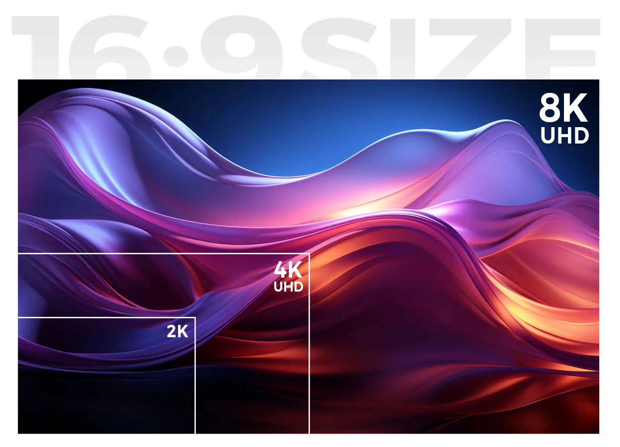
Apply the same relationship to height. As an illustrative calculation, a 4 × 2.25 m (13.1 × 7.4 ft) active area at an exact 1.25 mm pitch contains 3,200 × 1,800 pixels. This is below UHD 4K’s 3,840 × 2,160 pixels. The example assumes an achievable active area; actual cabinet combinations must be checked separately.
A processor accepting a 4K signal does not increase the physical pixel count. Verify the cabinet’s published pixel matrix, grid, and scaling behavior. EagerLED’s pixel pitch guide provides additional selection context.
02. Evaluate the offered configuration at operating conditions
Request luminance in nits (cd/m²), the intended calibrated brightness, grayscale performance, supported signal formats, and power figures with their measurement conditions. For COB LED technology, these are specifications to verify rather than benefits to infer.
Evaluate more than a single module when visual consistency matters. A multi-module sample can reveal joints and matching issues that one module cannot show. Use it to examine uniformity, then verify the complete delivered wall before acceptance.
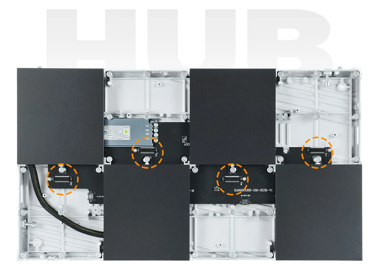
EagerLED’s EA600COB3 product page provides one indoor flip-chip COB reference with front-service modules. Treat the published family information as a starting point and request the exact pitch, module revision, and cabinet specification for the quotation.
03. Compare complete costs and installation responsibilities
A price per square meter is useful only when the included scope is clear. For a proposal using COB LED technology, request separate line items so that equipment omissions do not appear to be savings.
| Cost category | Clarify in the quotation | Potential omission |
|---|---|---|
| Display hardware | Pitch, native matrix, cabinet quantity, and module revision | Different hardware behind similar marketing descriptions |
| Video and control | Inputs, processing, receiving electronics, and required licenses | Missing switching, scaling, or control functions |
| Installation | Mounting, adjustment, power distribution, and ventilation | Site work outside the equipment price |
| Commissioning | Configuration, calibration, testing, and operator training | An assembled wall without an agreed handover |
| Service | Spare parts, repair terms, shipping responsibilities, and support | Unbudgeted downtime or return freight |
| Delivery | Packing, freight, insurance, and applicable import scope | Different delivery terms between quotations |
Separate operational energy estimates from electrical design. Expected running energy depends on measured average input power and operating hours. Circuit sizing requires the applicable maximum demand and project-specific electrical design, including relevant equipment characteristics and local requirements.
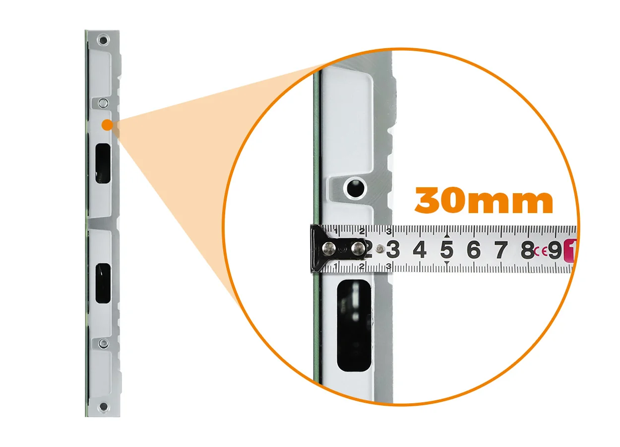
The installed depth includes mounting, adjustment, cabling, and ventilation space—not just the cabinet body. A qualified project team should confirm the structure and electrical provision for the complete assembly.
04. Agree acceptance and handover before ordering
A purchase involving COB LED technology should define visible-defect criteria, required tests, and responsibility for resolving exceptions. Record the approved settings and retain configuration backups, calibration files, spare-part identities, and service instructions. Ask who will support the system after installation and how a replacement component will be checked for visual matching.
9. FAQ
01. Is COB LED technology the same as MicroLED?
No. COB identifies an assembly approach, while MicroLED refers to very small LED emitters, with terminology varying across commercial products. A COB label alone does not establish the chip dimensions or qualify a screen as MicroLED. Request the emitter specification and construction details if a project requires a particular chip technology.
02. Does a COB LED display automatically support HDR?
No. HDR capability involves source formats, processing, signal handling, and the display’s achievable output. COB LED technology alone does not establish HDR compatibility or image quality. Confirm supported formats and the configured signal path, then evaluate highlight handling and shadow detail with suitable content at the intended operating settings.
03. Can I replace SMD modules with COB modules in an existing wall?
Do not assume a direct swap is possible. Mechanical fit is only one requirement; power, connections, drive electronics, receiving-card configuration, and calibration must also be compatible. Ask the original system supplier to assess the proposed conversion. The change may require new cabinets or electronics, making it a system replacement rather than a module upgrade.
04. Can a COB LED wall function as a touchscreen?
Only with a compatible touch-sensing system and the necessary software integration. An encapsulated surface does not detect touch by itself. Specify sensing method, interaction accuracy, latency, edge performance, and any additional protective layer. Test the complete touch assembly because overlays and mounting arrangements can affect both usability and image appearance.
05. How should spare COB modules be stored?
Follow the manufacturer’s packaging, environmental, and handling instructions for the exact module. Keep part numbers, production identification, and relevant calibration information with the spares. Do not assume encapsulation makes the electronics insensitive to moisture, contamination, or electrostatic discharge. Agree any inspection or conditioning procedure before putting a stored module into service.
06. Will sound pass through a COB LED screen?
Do not assume that a conventional solid-module LED wall is acoustically transparent. If loudspeakers would normally sit behind a projection screen, the audio layout needs review when changing to LED. Ask for acoustic data for any product marketed as acoustically transparent, and coordinate speaker positions with the AV and architectural design.
07. What should a warranty say about dead or stuck pixels?
It should define the applicable defect criteria, inspection conditions, coverage period, exclusions, and remedy. Ask how clustered defects, bright defects, surface damage, and replacement-module matching are handled. A general warranty duration does not explain whether a particular visual defect triggers repair, exchange, or another response.
08. Can modules from different production batches be mixed?
Use mixed batches only with supplier approval and a demonstrated visual match. Differences in emitters, surface treatment, electronics, or production revision may affect compatibility and appearance. Calibration may help with some variations but should not be assumed to correct every difference. Verify the result at operating brightness and under representative room lighting.
10. Conclusion
COB LED technology is a useful option when an indoor display needs fine pixel spacing and a protected emitting surface. The buying decision still depends on the actual image, installed environment, and service plan. Establish those requirements before choosing a product or accepting a packaging-based performance claim.
To assess COB LED technology for your project, send EagerLED the desired active dimensions, viewing distances, representative content, room lighting, installation constraints, and destination. Include camera or interactive requirements where relevant. Contact EagerLED for a configuration and itemized quotation, then compare the proposed hardware and demonstration results against the same written brief.