

An LED display power supply converts incoming electrical power into the regulated DC output required by the display's electronics. Choosing one requires more than matching a wattage label: the output voltage, available current, cooling conditions, input range, and cabinet connections must suit the approved display design.
For a project contractor reviewing a quotation, the most useful question is whether the proposed power system can support the specified screen under the conditions at the installation site. A successful demonstration in an open workshop does not establish performance inside a warm enclosure, after a power interruption, or with a different mains supply.
This guide explains how to evaluate an LED display power supply before approving a purchase or replacement. It includes an illustrative sizing calculation, a comparison of cooling arrangements, and practical requirements for a supplier's submittal. Numerical examples are calculation exercises, not EagerLED product specifications or measured project results.
1. What Does an LED Display Power Supply Do?
An LED display power supply delivers electrical energy to the module and control circuits. The driver electronics regulate how the LEDs are driven, while the receiving system determines the image. A supply does not set the screen's resolution, refresh rate, or grayscale capability by itself.
In a conventional cabinet, mains AC enters one or more switching supplies, which feed low-voltage DC circuits. Other architectures use an intermediate DC bus with conversion closer to the load. The relevant procurement document is therefore the cabinet's electrical diagram, not a generic illustration found online.
01. Separate the cabinet supply from the LED driver
The term “LED driver” can describe a constant-current lighting power unit or the driver ICs used in a display module. Those are different functions. A constant-current lighting driver is not automatically a substitute for the regulated voltage supply specified for an LED cabinet.
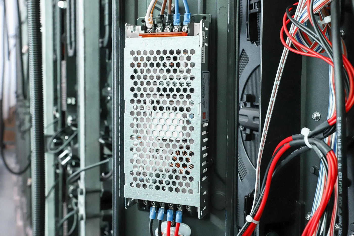
When requesting an LED display power supply, identify the exact cabinet, module revision, output requirements, and connector arrangement. A photograph of a metal enclosure is insufficient identification.
02. Separate capacity from energy consumption
The output rating describes a supply's available capacity under stated conditions. It does not mean the screen continuously consumes that amount. Energy use depends on the actual operating load and conversion losses.
Use EagerLED's LED display power consumption guide for operating-cost estimates. For component selection, establish the maximum supported demand and the conditions under which that demand can occur. These are related calculations with different purposes.
2. Match the Output Voltage and Power Architecture
The correct output voltage is the voltage specified for the connected electronics. Do not select a higher-voltage LED display power supply because it has more wattage, and do not lower the voltage simply because another cabinet advertises lower consumption.
01. Confirm every required DC rail
Some display designs use a single supply rail; others use separate rails or local conversion. Common-anode and common-cathode terminology describes circuit architecture, but it does not provide a complete wiring specification. Ask for the voltage, permitted tolerance, current requirement, and connected devices for each rail.
Check the receiving electronics and auxiliary loads as well as the LED modules. A module's voltage requirement does not establish the acceptable input for every other device in the cabinet.
For a multi-output LED display power supply, review the individual output limits and any combined-power restrictions. Unused capacity on one output may not be transferable to another.
02. Read the exact model column
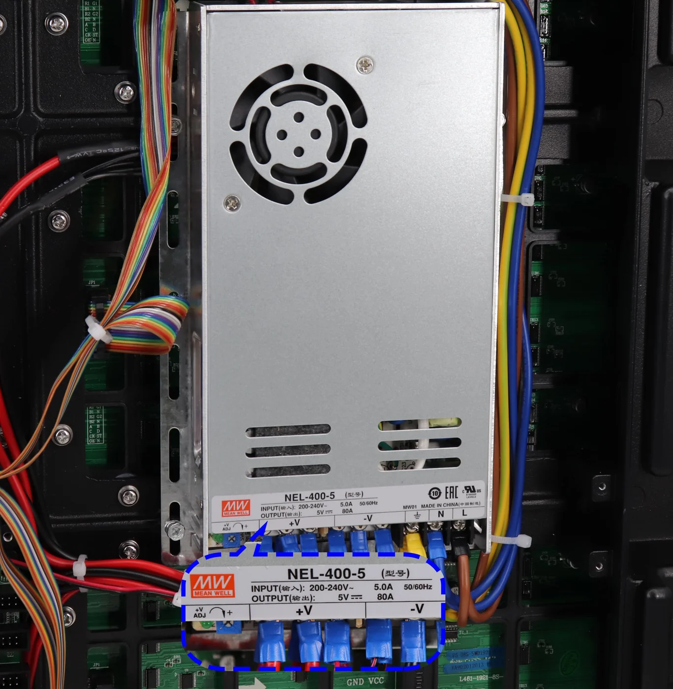
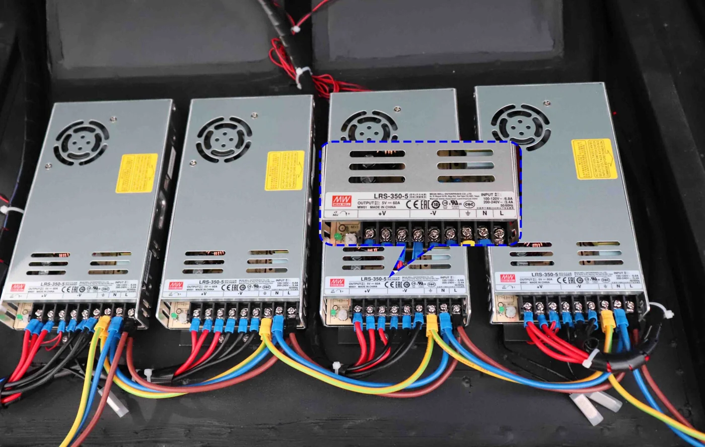
Product-family names can be misleading. In MEAN WELL's published LRS-350 specification, the LRS-350-5 variant is rated at 5 V, 60 A, and 300 W. The series name does not make that particular output a 350 W source.
This is an identification example, not a recommendation for an EagerLED cabinet. The same discipline applies to any supplier: read the exact voltage suffix, output current, and conditions in the model-specific documentation.
Require the supplier to identify whether the proposed setting is the nominal factory output or an approved adjustment. The available adjustment range is not proof that the connected modules tolerate every setting within it. Record the accepted voltage with the cabinet configuration so that future replacements use the same reference.
3. How to Size an LED Display Power Supply
Size an LED display power supply from the maximum supported DC demand assigned to it, then check its available output under the actual installation conditions. Do not use typical video-playback consumption as the sole basis for component capacity.
01. Build a load schedule for each supply
List the modules and other devices connected to each output. State whether the figures are DC load values, measured cabinet AC input, or estimates. Mixing those quantities can count conversion losses twice or omit them entirely.
For a regulated DC rail, power equals voltage multiplied by current. If a module's documented maximum current already includes its scan behavior, do not apply the scan ratio again. Confirm the brightness and configuration associated with the supplied figures.
| Connected load | Assumed maximum per item | Quantity | Combined demand |
|---|---|---|---|
| Display modules | 22 W | 8 | 176 W |
| Receiving and hub electronics | 8 W | 1 set | 8 W |
| Auxiliary devices on this rail | 6 W | 1 set | 6 W |
| Total assumed DC demand | — | — | 190 W |
All values in this table are hypothetical. At an assumed 5 V output, the total current would be 190 W ÷ 5 V = 38 A. This is the load to compare with available capacity, not a finished specification.
02. Apply the documented operating limits
Suppose a candidate LED display power supply is rated at 250 W, but its applicable operating curve permits only 80% of that output at the selected conditions. Its available output would be 200 W, leaving 10 W above the assumed load. These percentages are illustrative, not a universal derating rule.
If the project separately requires 20% reserve relative to the load, its capacity target becomes 190 W × 1.20 = 228 W. The hypothetical 200 W available output would not meet that target. A different model, cooling arrangement, or load allocation would need evaluation.
“Twenty percent extra capacity” and “operate at 80% loading” are different calculations. The latter would require 190 W ÷ 0.80 = 237.5 W. State the intended rule clearly in the specification.
03. Check the allocation, not just the total
Dividing total wall power by a PSU rating gives only a preliminary quantity. Each supply must support its assigned loads, and each branch must remain within its own limits. Spare capacity in a neighboring cabinet does not help an overloaded branch unless the approved distribution design allows it.
Ask for a cabinet-level allocation drawing alongside the arithmetic. That drawing makes the proposed LED display power supply quantity reviewable and helps maintenance personnel identify which modules each unit serves.
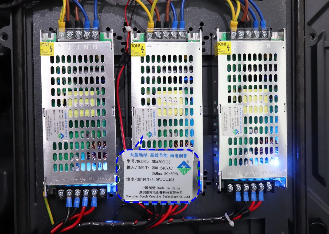
4. Check Temperature and Input-Voltage Derating
Derating is a reduction in allowable output under specified conditions. An LED display power supply may operate across a broad temperature range without delivering its full rated output throughout that range.
Read the manufacturer's curves and mounting instructions together. Depending on the product, allowable output can depend on ambient temperature, input voltage, airflow, orientation, or a specified case temperature. Do not automatically multiply several derating percentages unless the documentation defines that method.
| Condition | Evidence to request | Procurement decision |
|---|---|---|
| Air temperature near the supply | Cabinet thermal assessment or agreed test | Confirm usable output at the expected condition |
| Actual mains input | Applicable input range and derating curve | Verify suitability for the destination supply |
| Mounting orientation | Installation instructions and cabinet drawing | Confirm the rating applies in that position |
| Restricted airflow | Ventilation arrangement and clearance requirements | Resolve obstructions before approving the enclosure |
| Conduction cooling | Required mounting surface and thermal interface | Include those mechanical provisions in the scope |
An LED display power supply installed behind a display may experience a different environment from the room thermostat. Evaluate the air entering its cooling path and the manufacturer's specified measurement location. An open cabinet test should not be presented as evidence for a closed configuration without justification.
For international projects, “110 V compatible” or “220 V compatible” is not enough detail. Confirm the actual input range and whether input selection is automatic or manual. Some products have restricted ranges or different output capability at lower input voltage.
Record the intended enclosure, operating preset, input condition, and ambient assumptions in the approval package. If any of these change before delivery, request a review of the affected LED display power supply calculation rather than assuming the previous approval still applies.
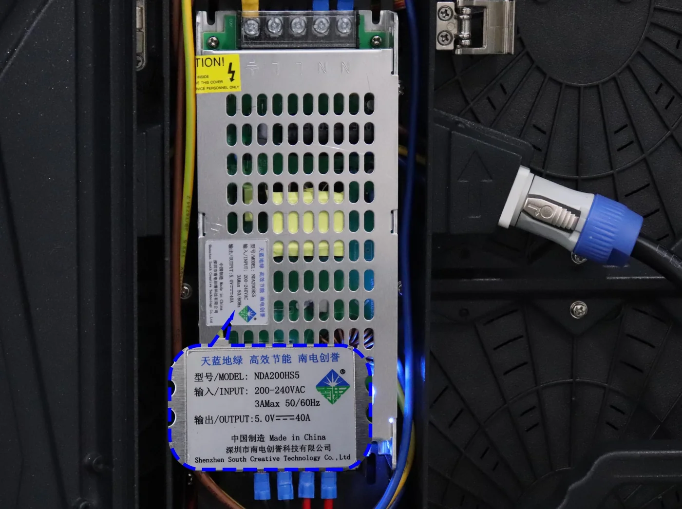
5. Understand Efficiency, Power Factor, and Inrush
Efficiency, power factor, and inrush current describe different behavior. A quotation that treats them as interchangeable leaves essential electrical questions unanswered.
01. Efficiency describes conversion losses
Efficiency is DC output power divided by AC real input power. For an illustrative 200 W DC load, 90% efficiency would require approximately 222 W of real input power, with approximately 22 W lost inside the supply. At 85%, the corresponding figures would be approximately 235 W and 35 W.
Those calculations compare hypothetical operating points. They do not establish savings for a particular LED display power supply. Compare published efficiency curves or measurements at equivalent input, output, load, and temperature conditions; a headline peak value may describe a different operating point.
02. Power factor affects input-current planning
For a single-phase input, real power equals RMS voltage multiplied by RMS current and true power factor. A power-factor value near one is not the same as high conversion efficiency.
The project electrical designer needs the relevant input-current information, not only the DC wattage. Active power-factor correction is a feature to evaluate against the project requirements; it is not a substitute for checking the complete system's electrical documentation.
03. Inrush concerns startup
Inrush is the brief current demand associated with energizing equipment. It is different from normal running current and from DC output load margin.
An LED display power supply that operates normally on its own may behave differently when many units start together on shared distribution. Ask the supplier and electrical contractor to review the intended switching sequence, protective devices, and documented startup characteristics.
Do not select a breaker from a general blog formula. The supply arrangement, fault protection, conductor ratings, and applicable local requirements belong in the project's electrical design. An operational test should then confirm that the approved startup sequence works with the installed equipment.
6. Compare Fanless and Fan-Cooled Power Supplies
The best cooling arrangement depends on the enclosure, acoustic requirements, service access, and approved operating conditions. “Fanless” does not mean that an LED display power supply can operate in a sealed, unventilated space at full load.
| Arrangement | Potential advantage | Constraint to verify | Evidence that matters |
|---|---|---|---|
| Natural convection | No internal fan noise or fan replacement | Air movement, orientation, and clearances remain relevant | Convection rating and installed temperature |
| Integral fan | Cooling is partly incorporated into the unit | Noise, dust exposure, fan behavior, and service access | Fan-control description and thermal requirements |
| Conduction cooling | Can support designs that transfer heat into a mounting structure | Performance depends on a specified thermal path | Baseplate limits and mounting instructions |
| External forced airflow | Cabinet airflow can cool several components | Rating may depend on the cabinet fan system | Required airflow and response to cooling failure |
For a quiet meeting room or worship space, evaluate audible noise at representative loading and temperature. A supply that is quiet during a short demonstration may behave differently once the enclosure warms up. Conversely, an integral fan is not automatically unsuitable if its measured operation meets the room's requirements.
For an outdoor installation, distinguish the cabinet's protection from the protection of each internal component. An enclosure's weather-resistance claim does not establish that a bare LED display power supply can be directly exposed to water or condensation.
Maintenance access also affects the choice. Confirm that technicians can extract the unit, reach its connections, and restore the intended cooling arrangement without damaging adjacent modules. A thinner enclosure is not a successful design if its power components cannot be serviced within the available access space.
When comparing quotations, ask each supplier to identify the cooling method for the proposed LED display power supply and the assumptions behind its rating. This provides a more useful comparison than selecting solely on enclosure thickness or the absence of a fan.
7. Review DC Distribution and Protective Functions
A suitable LED display power supply cannot compensate for an unsuitable distribution path. Cables, connectors, terminals, and branch protection must be evaluated with the connected loads.
01. Evaluate voltage where the load receives it
Voltage drop depends on current and the total resistance of the outgoing and return path. In a hypothetical branch carrying 20 A through 0.010 Ω of total path resistance, the drop is 0.20 V and resistive loss is 4 W. At a nominal 5 V source, that drop is 4% of the source voltage.
The example illustrates why apparently small resistance matters in low-voltage distribution. It is not a cable-sizing recommendation. Actual conductor selection also involves length, installation conditions, connector limits, and protection.
Do not increase the LED display power supply output blindly to correct a dim area. A loaded voltage problem may originate in a connection or branch, and a higher setting can affect other loads. Remote sensing, where supported, requires the exact manufacturer's instructions and does not remove conductor or connector limits.
02. Define what happens during a fault
Ask which protective functions are provided and how the supply recovers. Overload protection may shut down, limit output, or repeatedly attempt to restart, depending on the design. These behaviors have different consequences for the visible screen and for fault diagnosis.
Check the division of responsibility between the LED display power supply and downstream branch protection. A high-current source's own protection does not automatically establish adequate protection for every smaller wire or connector attached to it.
Protective functions should be verified through documentation and an approved test plan. Personnel should not create uncontrolled shorts or bypass protective devices to demonstrate a claim. Electrical connections and energized measurements require appropriately qualified personnel and suitable procedures.
8. Plan Replacement Compatibility and Redundancy
A replacement LED display power supply must be compatible electrically, mechanically, and thermally. Matching “5 V” and nominal wattage is only the beginning.
Check the exact output arrangement, polarity, terminal positions, mounting points, physical clearance, input selection, and required cooling. Confirm any alarm, remote-control, or current-sharing connections. A substitute can fit into the available space while changing the airflow or placing terminals beyond safe service access.
Keep an approved replacement list tied to the cabinet revision. The LED display spare-parts planning guide explains why inventory should be organized around compatibility and service needs rather than a generic percentage alone.
01. Distinguish spare units from live backup
A spare LED display power supply stored on a shelf reduces the delay in obtaining a replacement. It does not keep a failed circuit operating before a technician intervenes.
Likewise, installing two supplies does not automatically create redundancy. They may simply serve separate loads, with neither able to support the other circuit.
02. Require an approved parallel or redundant design
Parallel operation depends on the product's supported arrangement and the system design. Do not connect outputs together merely because both labels show the same voltage. Current sharing, fault isolation, available capacity after a failure, and monitoring require explicit consideration.
Specify what should remain visible after the agreed failure event and how an operator learns that redundancy has been lost. Use EagerLED's LED display redundancy guide to define the wider failover scope. A power-system claim should be checked separately from signal backup, because one does not establish the other.
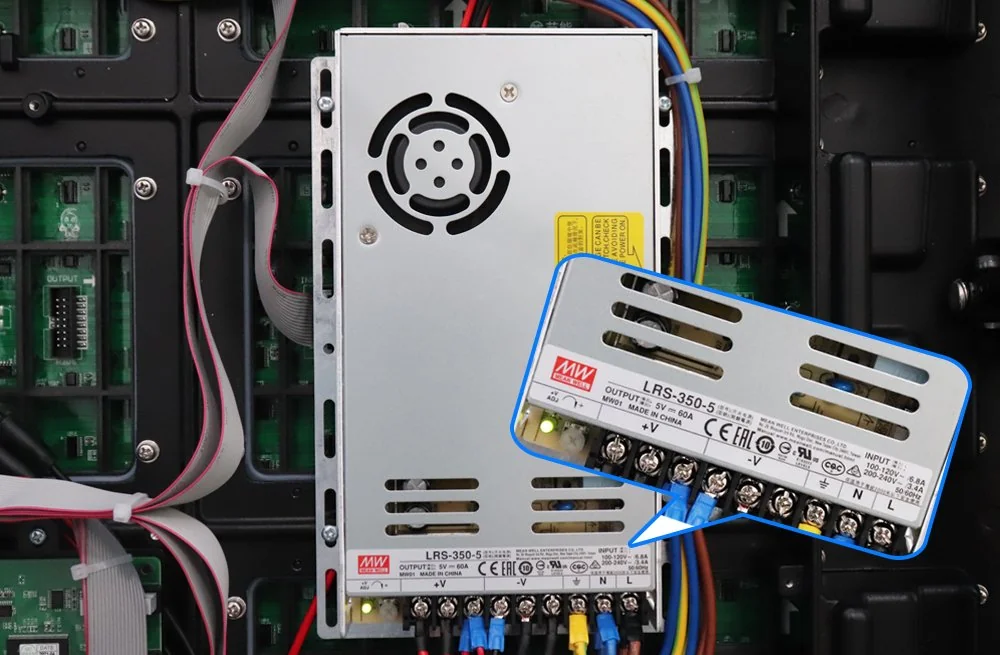
9. Specify the RFQ and Acceptance Tests
An LED display power supply quotation should identify the proposed component and demonstrate its suitability for the cabinet. A line that says “high-quality power supply included” is not enough for an engineering review or a future replacement order.
01. Request a reviewable technical submittal
| Procurement item | Supplier submission | Acceptance record |
|---|---|---|
| Component identity | Manufacturer, complete model, and revision | Installed label matched to the approved list |
| Output requirements | Rail voltages, current limits, and load allocation | Measurements referenced to defined load conditions |
| Available capacity | Rating and applicable derating basis | Calculation checked against the installation assumptions |
| Input behavior | Input range, selection method, and startup data | Agreed startup and restart sequence demonstrated |
| Cooling | Mounting and thermal requirements | Cabinet condition and measurement locations recorded |
| Serviceability | Removal procedure and approved alternatives | Access and replacement route demonstrated |
| Compliance documents | Records applicable to the exact supplied model | Scope and model identity reviewed |
| Handover | Drawings, parts list, settings, and fault contacts | Documents delivered in an accessible format |
Request applicable compliance records for the exact LED display power supply model and target market. A component document does not, by itself, establish conformity of the completed display installation. Keep component evidence and system-level responsibilities distinct.
02. Define the operating states to test
Agree on test conditions before shipment. The plan should cover the permitted high-load condition, representative content, and the intended operating presets. Record input conditions, brightness settings, cabinet configuration, and relevant temperatures so that later measurements can be compared meaningfully.
A full-white pattern may be useful, but it should not be assumed to represent every design's worst case without the manufacturer's confirmation. A brief startup demonstration also does not establish thermal behavior during sustained operation.
Ask the supplier to record the LED display power supply output and the voltage delivered at designated load points under the agreed conditions. Include startup, controlled shutdown, and recovery after the specified interruption. If redundancy is purchased, test the approved failure scenario and its monitoring indication.
03. Make faults traceable
The handover should let the contractor locate each supply, identify its loads, and obtain an approved replacement without guessing. Label the drawings and cabinet positions consistently. Record any approved adjustment, because an undocumented change can make later diagnosis unnecessarily difficult.
Accept the LED display power supply configuration against written criteria, not a statement that the screen “looks fine.” The final record should show what was installed, what was tested, which limits applied, and which party approved any departure from the original submittal.
10. FAQ
01. Can a higher-current supply damage a compatible module?
A compatible regulated-voltage supply does not normally force its full current rating into a functioning load. However, a higher-current replacement still needs approval: its protection behavior, fault energy, connectors, thermal requirements, and physical arrangement may differ. Matching voltage alone does not establish replacement suitability.
02. Does a larger LED display power supply always run cooler?
No. Temperature depends on conversion loss at the operating point and how effectively that heat leaves the unit. A larger rating does not guarantee lower loss, quieter operation, or better cooling inside the same cabinet. Compare the relevant efficiency and thermal information for the proposed configuration.
03. Can the display run from a generator or UPS?
Possibly, but compatibility must be reviewed at system level. Give the equipment designer the display's running demand, startup behavior, input requirements, and intended switching sequence. Include other connected equipment. A generator or UPS wattage label alone is insufficient to confirm suitable operation or runtime.
04. Does a black screen mean the power supply is off?
No. Showing black content can leave receiving electronics, drivers, and the power system energized. A software blackout is different from electrical isolation. Define operating, standby, shutdown, and maintenance-isolation procedures separately, and use the manufacturer's procedures for the equipment being serviced.
05. Can I replace an LED display power supply while it is energized?
Only a system explicitly designed and documented for the relevant hot-swap procedure should be treated that way, and only authorized personnel should carry it out. A removable or quick-release power box does not establish hot-swap capability. Otherwise, follow the approved isolation and service procedure.
06. Is every flickering or dark module a PSU fault?
No. Similar symptoms can arise from signal connections, configuration, module electronics, receiving equipment, or the DC distribution path. Record when the symptom occurs and which areas are affected. Qualified diagnosis should establish the cause before an LED display power supply is replaced or its output adjusted.
07. What does a long MTBF figure actually tell a buyer?
MTBF is a reliability metric tied to a stated method and operating assumptions. It is not a promise that an individual unit will operate for that duration, and it is not a warranty period. Request the basis of the figure and evaluate warranty, repair arrangements, and replacement availability separately.
08. Can common-cathode hardware use an existing cabinet supply?
Only if the complete electrical design approves that combination. The module may require different rails, connections, or current allocation. Treat an architecture change as a configuration review involving the module, distribution, controls, and LED display power supply, rather than assuming the existing unit remains suitable.
11. Conclusion
An LED display power supply should be approved as part of a documented cabinet power system. Start with the required rails and assigned loads, establish usable capacity under the installation conditions, and agree on the evidence needed for acceptance and replacement.
For an EagerLED project review, provide the screen dimensions, cabinet or module identification, destination mains supply, installation environment, service access, and any continuity requirements. If you are replacing a component, include clear label and connector photographs. Contact EagerLED with your project information so the proposed configuration can be checked against the actual display requirements.