


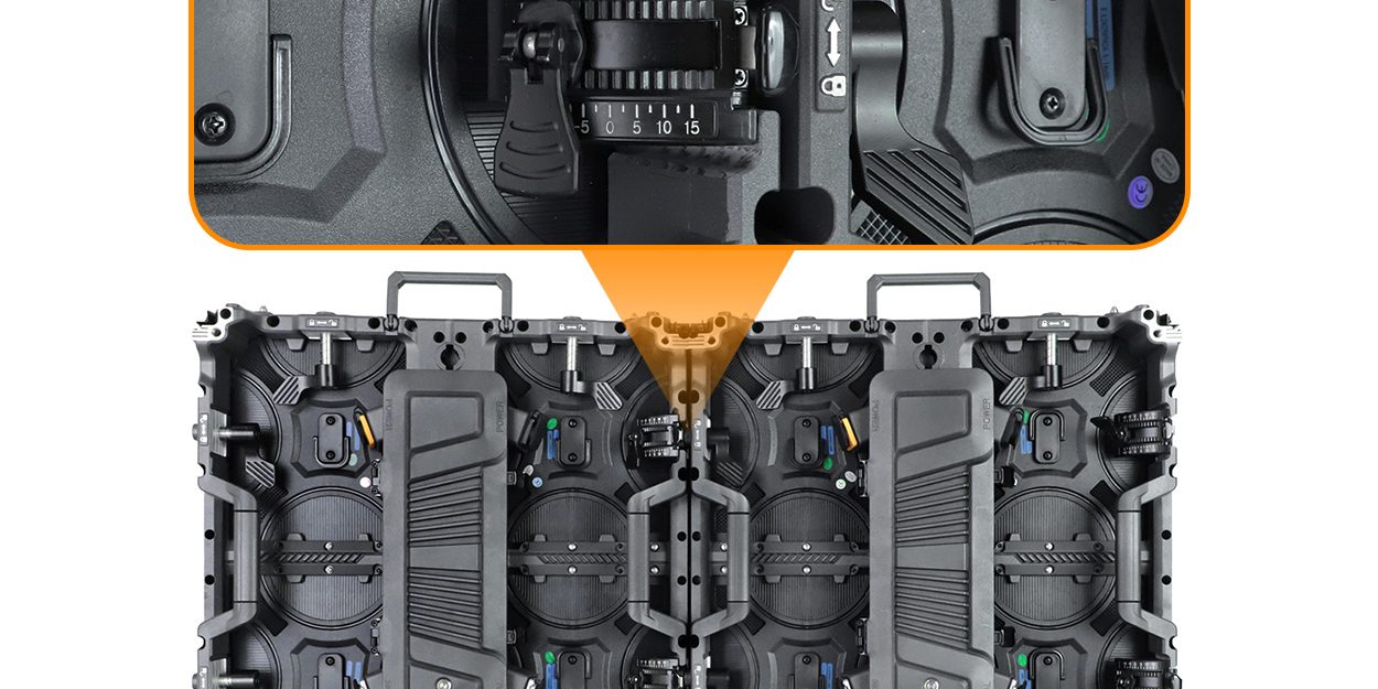
Shortlist concave rental LED wall suppliers by asking them to convert your stage plan into an identified cabinet grid and a supported angle at every joint. A statement that a cabinet “supports curves” does not establish the required radius, final footprint or compatibility with the ordered lock hardware. Approve those details before comparing the complete supply price.
Send a plan view that defines the audience side, curve direction, intended radius and its reference line. Request the exact cabinet and lock revision, permitted settings, complete support arrangement and a representative assembled demonstration. Keep the image geometry and the structural approval as separate deliverables.
In this guide
1. Define the curve before asking for a model
“Concave” should be unambiguous on the drawing: mark the viewing face and the center toward which the wall curves. Identify the line used for the radius, such as the front seam positions in a conceptual plan. A radius measured to support hardware or cabinet backs describes a different line.
State whether the design uses straight rigid cabinets forming facets, flexible modules, or another construction. Specify the wall height, cabinet orientation, stage footprint, open ends, flat transitions, scenic obstructions and camera positions. Do not combine geometry from different constructions under one “curved screen” label.
Our example uses straight 500 mm-wide cabinet faces forming equal facets. It is a geometry check for a supplier discussion, not a support design or an assertion that every cabinet can be installed at the calculated angle.
2. Check what the joint angle means for radius
For equal straight facets of width c, with a change in direction θ between adjacent faces, the circle through the facet endpoints has radius R = c ÷ [2 × sin(θ ÷ 2)]. Use consistent length units. This follows from splitting the isosceles triangle formed by the two radii and the cabinet-width chord.
| Geometric assumption | Calculation | Planning result |
|---|---|---|
| 500 mm straight facet; 3° joint angle | 0.5 ÷ [2 × sin(1.5°)] | Approximately 9.55 m radius |
| 500 mm straight facet; 6° joint angle | 0.5 ÷ [2 × sin(3°)] | Approximately 4.78 m radius |
| 500 mm straight facet; target radius 4 m | θ = 2 × arcsin[0.5 ÷ (2 × 4)] | Approximately 7.17° required between faces |
These are rounded mathematical examples, not measured cabinet limits. They neglect joint offsets, gaps, tolerances and hardware details. Use degrees for the angles shown; ask the supplier for the released geometry of the actual assembly. Swipe the table horizontally on a phone.
The practical purchasing question is whether the ordered lock can provide the required setting under the manufacturer’s approved arrangement. A fixed set of angle positions cannot be assumed to provide every intermediate radius. Do not round a requested angle to the nearest available setting without checking the changed stage footprint and obtaining design approval.
For a flat joint, θ is zero and this finite-radius formula does not apply; the row is straight. For flexible panels or joints with significant offsets, obtain the manufacturer’s specific geometry rather than applying the simplified rigid-facet example.
3. Tie angle claims to the exact lock revision
EagerLED’s EA500C6 product page describes 500 × 500 mm cabinets and optional concave or convex curve hardware. An EA500C6 curved-splicing article published on 22 October 2024 describes five positions: −6°, −3°, 0°, +3° and +6°.
That dated five-position description is useful for understanding why settings matter. It is not proof that all current EA500C6 orders use that same lock, or that the positive and negative signs match your drawing convention. Ask for the exact supplied lock, its angle definition, permitted positions and compatible cabinet revision.

For the simplified 4 m target above, a required 7.17° setting would not be established by a document listing only 3° and 6° magnitudes. That does not determine the capability of a different current lock. It identifies a question the supplier must resolve with an actual proposed assembly, rather than a generic “curved installation” checkbox.
4. Witness the proposed curve and flat transitions
Viewing points: watch the cabinet joining and angle-setting sequence in this official @EagerLED curved-assembly video. Use it to prepare questions about lock identification, direction and assembly order. The demonstration is not approval of a particular concert structure, radius or current hardware revision.
Request a representative row built with the proposed cabinets and locks. Include a curve-to-flat transition if the stage drawing contains one. Identify each position on a plan-view record and compare the front seams, ends and overall footprint with the supplier’s drawing. Record what was physically assembled; a short sample does not verify an entire concert wall.
For a multi-row wall, ask the supplier to explain how rows align and how the supported geometry is maintained through the height. Keep cable paths, service covers and component-removal routes visible in the demonstration. A shape that fits the front elevation may leave inadequate space behind the concave wall.
Have the responsible installation specialists approve the complete support, connections and site operating arrangement. A curve lock connects cabinets; its angle markings are not a load rating. Product demonstration footage does not replace the project’s structural and installation documents.
5. Approve content and viewing positions on the shaped canvas
Ask for both the cabinet map and the content canvas. State whether the creative intention is a continuous panorama, separate screen regions or a composition designed for particular camera positions. A flat artwork preview cannot show every effect of a faceted concave surface.
Review the normal show loop, important text, sponsor artwork and camera framing from the intended center and side positions. Retain the source format, mapping settings and observed limitations. If the production will film the screen, test the actual camera chain and settings; a refresh specification alone is insufficient evidence.
Keep any changed angle, cabinet count or transition in the revision record. Reconfirm the affected footprint and mapping before treating a different arrangement as approved. Do not reuse a previous flat-wall acceptance record as proof of the curved layout.
6. Compare a complete curved-system supply scope
Require cabinet and lock identities, quantities by size, curved and flat joint positions, matching electronics, control equipment, cables, spares and packing. State which support interfaces and installation documents are included. For Europe, identify the actual destination and responsible local integrator so applicable documentation and site requirements can be confirmed for that project.
Use the touring supplier acceptance checklist for fleet traceability, replacement parts and shipment handover. This guide adds the geometry review needed before accepting a concave stage design.
Send EagerLED a plan and elevation, marked audience side, radius reference line, required footprint, wall height, viewing and camera positions, indoor or outdoor conditions and delivery destination. Request an identified cabinet-and-lock proposal, supported angle schedule, mapping plan and the available assembly demonstration.
Discuss your concave concert wall drawing
Exact hardware, achievable geometry, support design and demonstration scope require project-specific confirmation.
7. Concave LED supplier FAQ
Does support for curved installation establish a particular radius?
No. Radius depends on cabinet geometry, joint settings and the actual assembly. Ask for the supplied lock revision and a cabinet-by-cabinet drawing that matches the stage plan.
What radius does a 500 mm straight facet form at 6 degrees?
In the simplified equal-facet model, R = 0.5 divided by twice the sine of 3 degrees, or approximately 4.78 m. This excludes joint offsets and tolerances and is not an installation approval.
Can an intermediate joint angle be assumed between two lock positions?
No. Obtain the permitted settings and approved adjustment method for the supplied lock. If the requested geometry changes, have the revised footprint and layout reviewed before accepting it.
Does the older EA500C6 five-position example apply to every current order?
No. The 22 October 2024 reference describes a particular five-position arrangement. Confirm the current cabinet and lock revision, angle convention and permitted configuration in the order documents.
What should remain after a curved-wall supplier demonstration?
Retain the identified hardware, angle schedule, plan and elevation, demonstrated assembly extent, content mapping, viewing observations, service constraints and unresolved issues with responsible owners.
Product page, dated assembly reference, illustration and official video checked 20 October 2026. Radius values are derived planning calculations; no measured performance, complete load capacity or universal current lock specification is claimed.