

LED display latency is the elapsed time between a defined input event and the corresponding visible change on an LED screen. It can describe the display subsystem or an entire camera-to-screen installation, depending on where measurement starts. Reducing it requires identifying delays throughout the signal path and testing the final configuration.
For an AV integrator preparing a live-event or corporate presentation system, a processor's advertised delay is only part of the answer. Cameras, computers, switchers, conversion equipment, receiving cards, and display scanning all influence when the audience sees an action. A technically accurate component specification can still produce an unsuitable project estimate if its measurement boundary is misunderstood.
This guide explains how to turn LED display latency into a useful purchasing requirement. It separates timing terms, examines operating-mode tradeoffs, and provides a measurement and acceptance framework. Numerical examples are calculations or explicitly hypothetical budgets, not EagerLED test results or performance guarantees.
1. What Is LED Display Latency?
An LED wall does not display every input change instantly. Information must be acquired or generated, transferred, processed, and converted into light. LED display latency measures the time between selected points in that process, usually in milliseconds or video frames.
Three boundaries matter when reviewing a proposal. Controller processing latency concerns a particular device and its documented input and output events. Input-to-light latency extends from an electrical video input to visible output at a specified screen location. Camera-to-screen latency starts with a physical scene event and includes the camera's contribution.
Interactive systems introduce another boundary: an operator's action, such as a button press, through application rendering to the resulting light. This is commonly described as input-to-photon or click-to-photon latency.
01. Read the endpoints before comparing numbers
Two suppliers can report different LED display latency values while describing identical hardware. One might measure from the arrival of the final input pixel; another might measure from the beginning of the input frame. Those intervals are not interchangeable.
Ask what starts the clock, what stops it, and which equipment is included. Also ask whether the result represents first visible change, a defined brightness threshold, or completion of the displayed transition.
02. Separate fixed delay from variation
A system may have a repeatable delay under stable conditions, yet change after a source switch or timing adjustment. Variable delay is often called latency variation or jitter, although the term needs a defined measurement context.
Record both the normal operating result and the observed spread across repeated tests. A single minimum LED display latency reading does not show what operators will experience throughout an event.
2. Where Does Delay Occur in an LED Video Wall System?
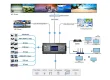
Delay can arise at several stages before the picture reaches the wall. Build a signal-flow drawing before replacing equipment; otherwise, the component with the most visible specification can receive attention while the dominant delay remains elsewhere.
| Stage | Potential contribution | What the integrator should verify |
|---|---|---|
| Camera | Exposure, sensor readout, image processing, output timing | Actual camera mode and output format |
| Computer or media server | Rendering queues, capture, composition, video output | Application settings and performance under load |
| Switcher or converter | Frame synchronization, scaling, format conversion | Enabled functions and timing behavior |
| Network video link | Encoding, buffering, transport, decoding | Codec, receiver settings, and network conditions |
| LED controller | Processing, mapping, synchronization, configured delay | Mode, firmware, canvas, and active features |
| Receiving electronics and panel | Receiver processing and light-output timing | Hardware compatibility, scan configuration, and measurement position |
The LED display latency budget should include only stages inside its declared boundary. If a vendor's measured subsystem figure already includes the receiving cards and panels, adding separate allowances for those stages would double-count them.
Illustrative budget: suppose a project allocates 25 ms to camera acquisition and output, 16.7 ms to upstream processing, and 16.7 ms to the LED subsystem. Assuming these describe consecutive, non-overlapping intervals, the planning total is 58.4 ms.
These figures are invented solely to demonstrate addition. They are not typical values, measured results, or a recommended acceptance limit. The completed path still needs direct measurement because buffering and synchronization can change the relationship between stages.
Record the path used by each important source. A presentation computer connected directly to the controller may behave differently from a camera routed through a production switcher.
Treat LED display latency as a property of the operating configuration. Changing the source route, processing preset, or output timing can invalidate an earlier result even when the cabinets remain unchanged.
3. Latency vs. Refresh Rate vs. Response Time: Key Differences
Refresh rate, frame rate, response time, and latency describe different behaviors. Confusing them can make an apparently strong specification answer the wrong purchasing question.
| Term | Meaning | What it does not establish |
|---|---|---|
| Source frame rate | Number of video frames supplied each second | Total delay from a real event to the screen |
| LED refresh rate | Repetition rate associated with LED driving and light output | Number of unique source images shown each second |
| Pixel response time | Time for a defined light-output transition | Waiting time elsewhere in the video chain |
| Processing latency | Delay through a defined processing stage | Complete camera-to-screen delay |
| Synchronization | Timing relationship between devices or signals | Absence of buffering or processing delay |
A display specified with a 3,840 Hz LED refresh rate does not receive 3,840 unique video frames each second from a 60 fps source. That refresh figure alone cannot establish LED display latency. EagerLED's high-refresh-rate display guide discusses the separate relationships between refresh, source timing, and camera performance.
Frame-based specifications need a frame rate:
Frame duration in milliseconds = 1,000 ÷ Frames per second
| Video frame rate | One frame | Two frames |
|---|---|---|
| 24 fps | 41.67 ms | 83.33 ms |
| 25 fps | 40.00 ms | 80.00 ms |
| 30 fps | 33.33 ms | 66.67 ms |
| 50 fps | 20.00 ms | 40.00 ms |
| 60 fps | 16.67 ms | 33.33 ms |
| 120 fps | 8.33 ms | 16.67 ms |
Values are rounded calculations for the stated rates. Fractional rates such as 59.94 fps require their own calculation.
A two-frame specification at 60 fps therefore represents a different elapsed interval from two frames at 30 fps. However, increasing source frame rate does not guarantee that every device becomes faster: supported formats, rendering load, buffering, and output scheduling still matter.
Request LED display latency in milliseconds, accompanied by the source frame rate and the manufacturer's frame-count definition.
4. How Much Latency Is Acceptable for Different Applications?
There is no single acceptable LED display latency limit for every installation. The relevant question is what viewers compare the screen against: a live performer, their own action, another display, or a prerecorded soundtrack.
| Application | Main timing concern | Useful acceptance demonstration |
|---|---|---|
| Live image magnification, or IMAG | Screen image trails the visible performer | Show a live speaker and rapid physical movements |
| Corporate presentation | Pointer, annotation, or camera response feels delayed | Use the actual presentation and conferencing workflow |
| Interactive installation | User action and visual feedback feel disconnected | Test the complete sensor or input-device path |
| Broadcast or virtual production | Timing affects capture, tracking, or background alignment | Test the intended camera, tracking, and synchronization setup |
| Prerecorded signage | Playback coordination matters more than response to live action | Check scheduled content and transitions across displays |
For live IMAG, the audience may see the person directly and on the screen simultaneously. Evaluate the image delay separately from audio alignment. Loudspeaker processing and acoustic travel time introduce another timing problem that varies across listening positions.
For an interactive exhibit, a low-delay LED wall cannot compensate for a slow application or sensor. Measure from the visitor's action if that is what determines satisfaction.
In virtual production, tracking, rendering, camera capture, and display timing must work together. A controller-only figure does not describe the entire motion-to-photon or camera capture workflow.
Establish the project's LED display latency target before comparing quotations. Specify the application, measurement boundary, operating format, maximum acceptable result, and required visual demonstration. Agree on the threshold with the production team or system designer rather than presenting an unsupported universal number.
The fastest available mode may also remove a feature the project needs. A slightly longer but stable path with required composition and synchronization can be a better fit than a shorter path that cannot run the show.
5. Standard vs. Low-Latency Modes: Benefits and Limitations
Low-latency modes can shorten processing or alter how data travels through a compatible system. Their benefits and restrictions depend on the controller, receiving hardware, firmware, and screen configuration.
Do not assume that a setting labeled “Low Latency” preserves every other feature.
| Configuration choice | Potential benefit | Limitation to investigate |
|---|---|---|
| Standard processing | Retains supported composition and conversion functions | May involve additional processing delay |
| Send-only operation | Can remove a processing stage | Upstream equipment may need to prepare the final canvas |
| Low-latency controller mode | Shortens the supported video path | May restrict synchronization or other functions |
| Compatible receiver mode | Can reduce downstream delay | Requires supported receiving cards and panel configuration |
| Higher input frame rate | Shortens each source frame interval | Increases format, bandwidth, or rendering demands |
One documented example appears in NovaStar's CX40 Pro Specifications V1.5.0: Send-Only mode can reduce latency by one frame, while All-In-One mode provides layer and scaling functions. This is a model-specific distinction, not a rule for every LED controller. See the CX40 Pro specification hosted by EagerLED.
For an LED display latency comparison, retain the functions required by the project. A demonstration using a prepared test canvas cannot prove the result of a production workflow that needs multiple sources, scaling, and format conversion.
01. Verify the complete compatible configuration
Ask the supplier to identify the controller, receiver, firmware, cabinet pixel dimensions, and relevant settings. Some implementations impose requirements on port mapping or cabinet connection direction.
The physical screen can look correct while its configuration prevents a particular low-latency mode from operating as intended. Save the accepted mapping and configuration files with the project record.
02. Test image quality in the selected mode
After changing modes, inspect gradients, fine text, low-brightness content, and camera output where relevant. Verify required color and processing functions individually.
A useful LED display latency improvement preserves the agreed operating requirements. Record both the time saved and any feature or image-quality tradeoff; an isolated timing number cannot describe the result adequately.
6. Does Genlock Reduce LED Wall Latency?
Genlock aligns video timing to a reference. It can help establish predictable timing relationships, but it does not automatically remove processing delay or make every connected device display the same moment.
A frame synchronizer performs a related but different job: it buffers an incoming signal so that output can follow the required timing. Synchronizing an untimed source can therefore involve added delay.
When investigating LED display latency, distinguish the reference arrangement from the actual buffered path. Two devices can share a reference while presenting different source frames because one path contains additional processing.
Compatibility also needs explicit checking. The CX40 Pro V1.5.0 specification states that its Low Latency function cannot operate simultaneously with Genlock. It also recommends vertical cabinet loading and a common starting Y coordinate when Low Latency is enabled. Confirm those conditions against the supplied configuration and documentation version. Source: CX40 Pro Specifications V1.5.0.
Do not generalize that restriction to every controller family. Other systems have different timing architectures and supported combinations.
For a multi-screen installation, measure each complete path before applying compensating delay. Aligning a faster screen with a slower screen improves relative timing, but it increases the faster path's absolute delay.
Assess LED display latency and synchronization as separate acceptance items: one describes elapsed time, while the other describes how required events relate.
7. How to Measure End-to-End LED Display Latency
Measure LED display latency using a repeatable input event, a defined visible output event, and an instrument appropriate to the required accuracy. Decide the boundary before choosing the test equipment.
01. Choose a method that answers the question
For a practical relative comparison, send the same changing test signal to a reference display and the LED wall, then record both together using a suitable high-speed camera. Match the relevant image regions and examine multiple transitions.
This shows the difference between the two paths. It does not establish absolute input-to-light delay unless the reference path is independently characterized.
For camera-to-screen assessment, a recording can include a physical visual event and its reproduction on the wall. The production camera must remain inside the measured path; the observing camera records both endpoints.
A photodetector-based setup offers another approach: timestamp a defined event and detect the corresponding light change on the display. The detector, trigger arrangement, threshold, and instrument timing need characterization.
02. Understand the limits of a camera recording
At an actual capture rate of 240 fps, consecutive recorded frames are approximately 4.17 ms apart. That interval describes sampling granularity, not guaranteed measurement accuracy.
Exposure duration, rolling-shutter timing, screen scanning, and ambiguous transition edges can introduce uncertainty. Keep compared image regions at similar positions in the observing camera's frame where practical, and document any remaining timing differences.
Use original recorded frames and verified capture timing. A slow-motion clip's playback rate is not necessarily its recording rate.
03. Record the operating conditions
| Record | Why it is needed |
|---|---|
| Start and stop events | Defines the measurement boundary |
| Signal-flow drawing | Identifies included equipment and bypassed stages |
| Source resolution and frame rate | Makes frame-based comparisons meaningful |
| Controller, receiver, and firmware | Connects the result to a reproducible configuration |
| Processing and synchronization settings | Identifies the active operating mode |
| Screen test position and pattern | Controls spatial and content-related differences |
| Instrument settings and uncertainty | Shows what the measurement can resolve |
| Repeated results and operating state | Reveals variation and mode-dependent behavior |
LED display latency can differ by screen location because the displayed image is not necessarily updated everywhere simultaneously. Test representative positions and state whether acceptance uses a particular position or the worst observed result.
Repeat the measurement after warm-up, preset recall, source changes, and other operations relevant to the project. Report the sample count, range, and agreed summary statistic.
Finish with the intended production content. A timing test establishes delay; it does not by itself prove that the system retains all required functions.
8. How to Reduce Input Lag Across the Video Signal Chain
Reducing LED display latency starts with removing avoidable work in the signal path before replacing panels. Begin with a stable baseline and change one variable at a time so that each improvement can be attributed to a specific action.
01. Remove unnecessary conversion and processing
Compare the normal route with a supported direct connection. Bypass an unused scaler, capture stage, or network-video link temporarily, then measure the difference.
Where practical, prepare content at the required canvas and output timing. This may eliminate redundant scaling or frame-rate conversion, but confirm that the chosen format is supported throughout the chain.
An LED display latency reduction measured during bypass testing identifies an opportunity; it does not automatically authorize removing equipment needed for switching, resilience, or production control.
02. Check the source computer under real load
A media server may behave differently with a demanding composition than with a simple test pattern. Check rendering performance, capture paths, output settings, and application queues while running representative content.
Use supported settings and document any changes. Reducing queues can affect smoothness or stability if the computer cannot sustain the required workload.
03. Validate the controller and receiver configuration
Enable the appropriate documented mode only after confirming compatibility. Recheck port mapping, input timing, synchronization, and any additional delay settings.
Compare before-and-after results under identical conditions. If the difference is smaller than measurement uncertainty, do not report a precise improvement.
Once LED display latency meets the agreed requirement, save the working configuration and stop making unrelated timing changes. A reproducible setup is easier to commission, support, and restore than an undocumented collection of adjustments.
9. How to Specify a Low-Latency LED Display Before Buying
Specify a measurable outcome for the intended workflow. “Low latency,” “real time,” and “zero delay” are incomplete purchasing requirements without a boundary, operating conditions, and acceptance method.
An LED display latency request should identify the source types, screen resolution, video formats, necessary processing features, camera requirements, and normal and backup paths. Suppliers can then explain which configurations support the complete requirement.
| Specification item | Required detail |
|---|---|
| Application | Live IMAG, presentation, interaction, or camera-background workflow |
| Timing boundary | Defined source event through a specified visible screen event |
| Performance limit | Agreed milliseconds and any frame-based equivalent |
| Operating configuration | Resolution, frame rate, receiver, firmware, and processing mode |
| Required functions | Scaling, layers, synchronization, color processing, and redundancy |
| Test procedure | Equipment, test pattern, measurement positions, and repetitions |
| Acceptance record | Results, uncertainty, saved settings, and approved configuration |
| Change control | Retesting requirements after substitutions or relevant updates |
Keep performance commitments tied to the delivered bill of materials. A controller substitution or receiving-card change may alter which functions can operate together.
For projects considering a COEX configuration, EagerLED's CX40 Pro controller guide provides background on modes, receiving-card compatibility, and screen planning. Treat it as preparation for configuration-specific discussion, not a guarantee for an unspecified installation.
Require the supplier to state any exceptions before order placement. If the proposed LED display latency can only be achieved without a required feature, resolve that conflict during design rather than discovering it at acceptance.
Finally, allocate responsibility across contractors. The display supplier can verify the supplied subsystem; the integrator must also validate the camera, production, transport, and source components within the complete project boundary.
Approve LED display latency on the assembled operating system, with the agreed settings preserved for handover.
10. FAQ
01. Does a smaller pixel pitch automatically reduce LED display latency?
No. Pixel pitch describes physical pixel spacing, not the time required to process and display a signal. A finer-pitch wall may change total pixel load and controller requirements, but delay depends on the complete hardware and operating configuration. Compare systems at their required resolution and supported modes.
02. Does increasing the physical screen size always add delay?
No. Size alone does not determine delay. A larger installation may require additional processors, different port maps, or more complex distribution. Those changes can affect timing, so verify the actual architecture instead of assigning a fixed delay per square meter or cabinet.
03. Can fiber-optic cabling eliminate video delay?
No. Fiber transports signals; it does not remove camera exposure, rendering, buffering, or controller processing. The converter or transmission system may also perform functions that affect delay. Select fiber for the required distance, bandwidth, and installation conditions, then measure the complete path.
04. Will an internet speed test reveal LED display latency?
No. An internet speed test measures characteristics of an internet connection. It does not measure when a local video input becomes visible on the wall. If streamed content is involved, streaming and network delays are additional parts of the chosen measurement boundary.
05. Can I fix delayed video by adding audio delay?
Adding audio delay may align sound with an already delayed image for a particular playback path or listening position. It does not make the image arrive sooner. Live venues require coordination with the audio designer because direct sound, loudspeaker coverage, and acoustic travel time vary across the room.
06. Is backup-switching time the same as normal video latency?
No. Steady-state latency describes normal signal transit. Failover time describes the interruption or transition when the system changes paths. Specify and test both. Also measure the backup path after switching, because its ongoing delay may differ from the primary path.
07. Should LED display latency be retested after a firmware update?
Retest when an update or configuration change can affect processing, synchronization, receiver behavior, or enabled features. Preserve the previous approved versions and settings according to the supplier's recovery procedure. A successful image after updating does not demonstrate that the original timing requirement is still met.
08. Does choosing HDMI instead of SDI guarantee lower latency?
No. Connector type alone does not determine system delay. Input processing, supported formats, conversion stages, and device modes all matter. Compare the actual supported routes with the same source event and output measurement, rather than assuming that one interface is always faster.
11. Conclusion
A useful LED display latency specification tells everyone exactly what must be measured, under which conditions, and with which functions enabled. Start with the application, define the timing boundary, and verify the proposed configuration before making a purchasing commitment.
For an EagerLED inquiry, prepare your source and camera models, signal-flow drawing, screen resolution, required video formats, processing features, and acceptance target. Discuss the project requirements with EagerLED and request a compatible configuration with a documented verification method. Confirm LED display latency again during commissioning so the delivered system matches the approved operating requirement.