

LED screen components include the light-emitting modules, cabinets, power supplies, control electronics, cables, supporting structure and equipment needed to operate the installation. A useful way to understand them is to follow three paths: video data to the pixels, electrical power to the electronics, and mechanical loads to the building or support.
This guide explains direct-view LED displays, rather than the LED backlight inside an LCD television. It helps buyers, distributors, AV integrators and project contractors compare a bill of materials, identify compatibility questions and prepare a service plan.
Use this LED screen components list to follow the display body, control system, frame structure and auxiliary equipment from specification to handover. The tables explain each part’s function and the questions to ask before buying. Product examples are model-specific, so confirm the exact configuration for your project.
1. Display body and LED screen components
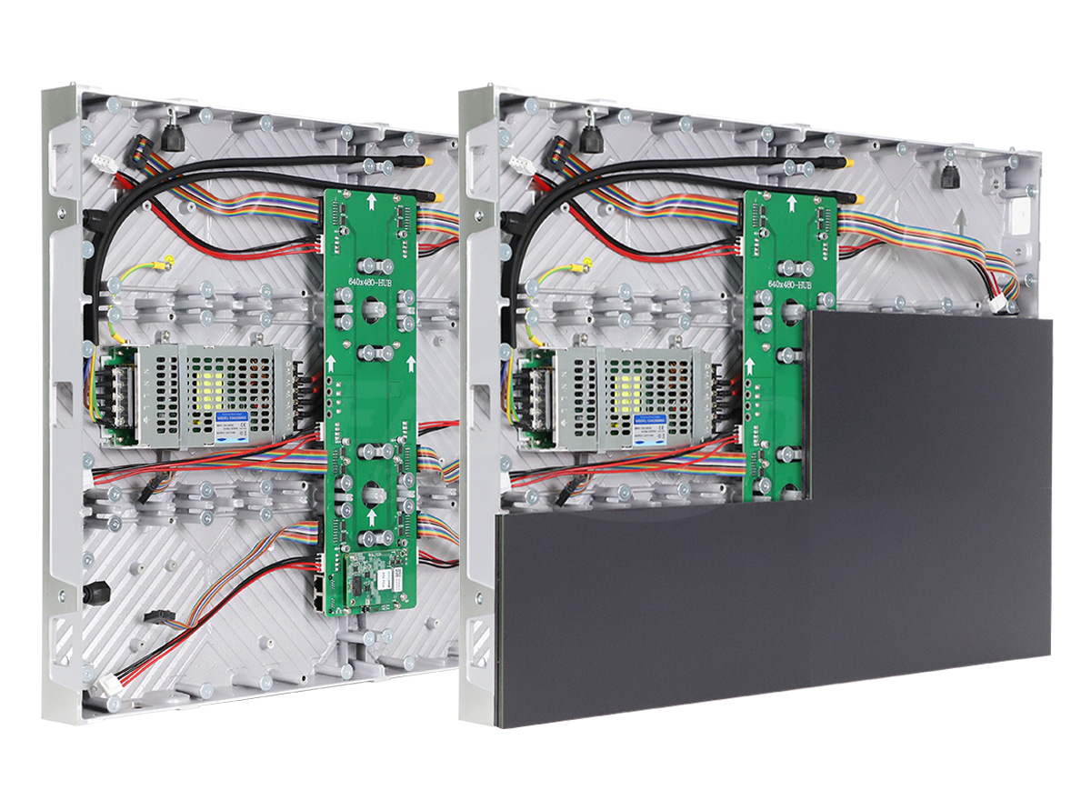
The display body contains the LED screen components at the visible wall and directly behind it. Modules contain the pixels and their supporting circuitry; cabinets hold groups of modules in an aligned, serviceable assembly. The cabinet may also contain power supplies, receiving electronics, adapter boards and connections, depending on the design.
When comparing LED screen components, distinguish a module from a cabinet. A supplier may describe either item as a “panel,” so ask for dimensions, pixel resolution and an assembly drawing. A quotation for loose modules is not equivalent to a complete cabinet ready to join a screen.
01. LED screen components: modules, pixels and driver ICs
A pixel combines red, green and blue light to produce the image. Pixel pitch describes the spacing between neighbouring pixel centres. Smaller pitch increases pixel density for a given physical area, but it does not by itself establish the correct choice for the viewer, content or budget.
Modules include more than the visible LEDs. Circuit boards and driver electronics distribute the image information and regulate light output. Package construction, driver configuration, scan arrangement and calibration affect how the module works with the rest of the system. Treat these as compatibility requirements for LED screen components, not optional details on a spare-parts order.
For example, the EagerLED EA640F2 indoor display uses a 640 × 480 mm cabinet and 320 × 160 mm modules. Six of those module footprints fill that cabinet face in a two-by-three arrangement. This is a model-specific example; other cabinets use different layouts.
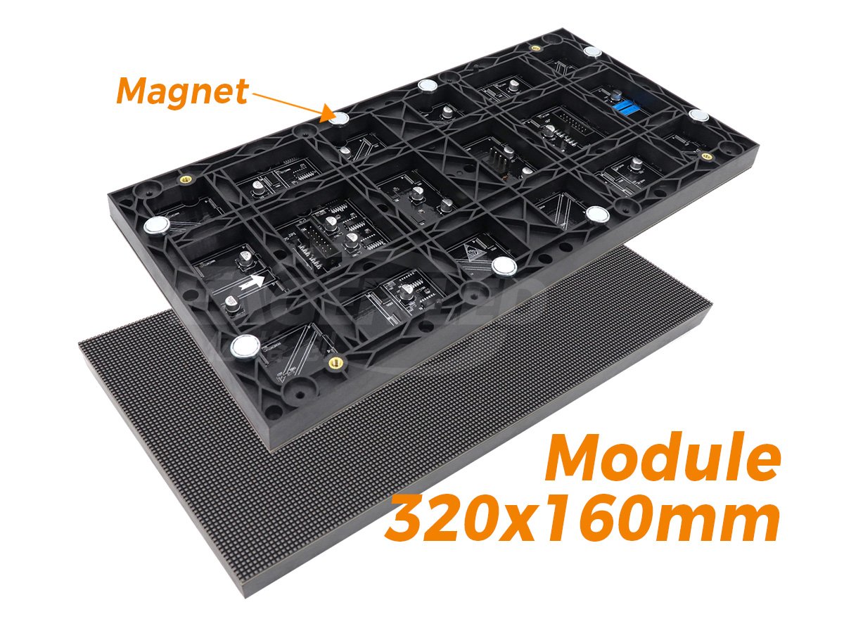
Specify the exact module model, pitch, pixel matrix, connector arrangement, electrical requirements and revision. Two LED screen components can fit the same opening yet use different driver settings or colour characteristics. A physically successful replacement can still produce a visibly mismatched image.
| Component | Main function | Procurement check |
|---|---|---|
| LED module | Creates a defined portion of the image | Pitch, matrix, dimensions, driver configuration and compatible revision |
| Cabinet | Aligns modules and holds serviceable assemblies | Dimensions, weight, flatness, access method and connection details |
| Driver electronics | Controls pixel output according to module configuration | Supported scan arrangement and matching configuration files |
| Power supply | Converts the specified input supply to required DC power | Output voltage, capacity, protection and model-specific connections |
| Adapter or HUB board | Routes control signals and, in some designs, power | Pinout, receiver interface, module compatibility and revision |
| Internal cables and connectors | Connect the assemblies within the cabinet | Type, orientation, current capacity, routing and identification |
02. Power supplies and service access
Power supplies are critical LED screen components because an otherwise correct image chain cannot operate without the required electrical supply. Use the voltage and connection scheme specified for the installed design. Do not assume every module or receiving card uses the same DC voltage merely because the cabinets look similar.
Separate maximum system demand from typical energy use. The maximum demand informs the project electrical design; average consumption depends on content, brightness and operating conditions. Qualified electrical personnel should determine circuit protection, conductor sizing and grounding from the actual system documentation and local requirements.
Ask how serviceable LED screen components can be reached once the display is mounted. Front-access modules do not necessarily mean every power or control assembly is equally accessible. Have the supplier demonstrate the complete replacement route, including tools, clearance, isolation and the space needed to hold a removed module.
Record the LED screen components installed in each cabinet position. Include module revisions and spare stock in the same register. This helps technicians select the correct replacement and helps the buyer compare a future repair quotation with the equipment actually supplied.
2. Control system and compatible LED screen components
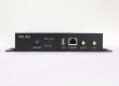
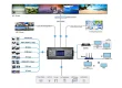
The control system converts the source content into data that the display can show. A typical synchronous chain is video source, processor or sending controller, data links, receiving cards, module interfaces and pixels. Some products combine several functions in one device; asynchronous players can store and schedule content locally.
A computer with a separate sending card is one possible arrangement, not a universal requirement. When specifying LED screen components, ask who supplies the source player, which inputs are required, where scaling happens and whether playback must continue without a network connection.
01. Follow the image from source to cabinet
The processor may scale, crop or arrange sources to fit the physical pixel canvas. Receiving cards distribute the appropriate data to connected modules according to the configured mapping. A correct total pixel count does not automatically guarantee that every port, cabinet row and module arrangement is supported.
Receiver loading limits depend on the exact product and operating conditions. For example, the official NovaStar MRV412-N specification, version 1.0.3 lists different maximum resolutions for PWM and common driver ICs at a stated source bit depth and frame rate. Use the applicable configuration limits instead of assuming one universal pixels-per-card figure.
This distinction matters when ordering LED screen components for a repair or expansion. A card with sufficient headline capacity may still need a different connector arrangement, firmware or configuration. Ask the integrator to document the supported combination and retain a known working configuration before any service change.
| Interface | Confirm together | Practical acceptance check |
|---|---|---|
| Source to processor | Connector, resolution, frame rate and required content format | Play the real source without cropping or unsupported modes |
| Processor to receiving system | Compatible ecosystem, port loading and data route | Verify the complete cabinet map and image continuity |
| Receiver to module interface | Pinout, scan configuration, driver support and module matrix | Check colour patterns, orientation and low-level content |
| Primary and backup paths | Supported redundancy mode and physical connections | Demonstrate the agreed failure behaviour under supervision |
| Content management to player | File formats, permissions, scheduling and offline behaviour | Expire a test item and restore an approved playlist |
02. Keep the files that make the hardware usable
Configuration records are as important as physical LED screen components. Keep the screen map, receiver configuration, calibration data where applicable, controller settings and compatible software versions. For NovaLCT installations, see our guide to backing up and restoring NovaLCT configuration files. Store an accessible backup with a clear date and a note describing the installation it belongs to.
Do not load an unknown configuration file into a working display merely because its cabinet dimensions match. Request the file for the actual module and receiver combination. Test replacements through the manufacturer’s documented procedure and retain a rollback route for the known working setup.
Label data cables by destination, cabinet position and port. Distinguish LED data connections from the ordinary office network, even when both use familiar connector shapes. Use only the cable type, link distance and topology supported by the selected control system.
For filmed presentations, test the intended camera settings with the actual display configuration. Refresh specifications alone do not establish a camera-compatible result in every operating mode. Include the camera, shutter setting, brightness and representative content in the acceptance record if recording is part of the project.

3. Frame structure and installation interfaces
The supporting structure transfers the installation’s loads to its approved support. Cabinets, mounting frames, fasteners and the building interface must work together. A cabinet’s locking mechanism is not, by itself, evidence that an arbitrary wall, hanging arrangement or outdoor support can carry the system.
When procuring LED screen components, separate the cabinet assembly from the project structure. Establish who designs the frame, checks the supporting surface and approves the attachment details. The equipment supplier, structural designer and installer need a common set of dimensions and responsibilities.
01. Distinguish fixed and rental arrangements
A fixed indoor wall may use a supporting frame aligned to the cabinet grid, while a rental installation may require an approved hanging or ground-support system. These are different design conditions. Do not assume rental locks, brackets or stacking limits apply across cabinet families.
Outdoor work also needs project-specific consideration of wind, water management, corrosion exposure and maintenance access. Refer those requirements to the relevant qualified professionals and the supplied system documentation. A product protection rating does not establish the safety of the supporting structure or the complete installed enclosure.
Obtain drawings that show both the display face and the space behind or in front of it. Include cable entries, isolation points, removable covers and access equipment. LED screen components that are easy to reach on a workshop bench may become inaccessible after decorative finishes are installed.
| Interface | Required information | Responsibility to confirm |
|---|---|---|
| Cabinet to frame | Grid dimensions, attachment details, alignment and permitted mounting method | Display supplier and installer |
| Frame to building | Support condition, design loads and approved attachment drawings | Qualified structural designer and building representative |
| Power to display | Maximum demand, circuit arrangement, isolation and protective measures | Project electrical designer and electrician |
| Screen to service route | Clearances, lifting route, access restrictions and safe working method | Installer and maintenance provider |
| Outdoor enclosure to environment | Drainage, sealing, cooling and documented environmental limits | System designer and relevant contractors |
02. Inspect alignment before covering the structure
Inspect cabinet joints, face alignment and accessible connections during installation. Record issues before the structure is concealed. For LED screen components, a small mechanical mismatch can make a seam visible or complicate module removal, even when every pixel lights correctly.
Agree on the method for checking alignment and the acceptable result before delivery. Use the supplier’s tolerances for the specific cabinet and the project’s acceptance criteria. Do not substitute a universal tolerance quoted without reference to the proposed system.
Keep the final installation drawings with the asset register. If a future team adds cabinets, changes the support or encloses the rear, it needs the original design assumptions. An extension is a new engineering check, not merely an order for additional LED screen components.
4. Auxiliary equipment, maintenance and acceptance
Auxiliary equipment supports operation but varies with the project. It can include a content player, network connection, control workstation, electrical distribution equipment, environmental monitoring, cooling equipment and service tools. Audio equipment is needed only when the application calls for sound.
Not every installation needs an industrial computer, air conditioner or the same type of fan. Choose these items from the environment, heat load and operating workflow. The list of LED screen components should reflect the approved design rather than copying a generic accessory package into every quotation.
01. Build a useful bill of materials
A procurement-ready bill of materials identifies the supplied LED screen components, quantities, revisions where relevant, spare allocation and responsible supplier. Distinguish supplied hardware from work by others. Include software licences or subscriptions when they are needed for the agreed operating functions.
Consider an illustrative cabinet layout with five cabinets across and three high. It contains fifteen cabinets. If each cabinet uses six modules, the installed module count is ninety. That calculation does not determine receiver or power-supply quantities: those LED screen components follow the actual cabinet design and loading plan.
Ask for spares based on the maintenance strategy, repair lead time and compatibility risk. A percentage alone is not a complete plan. Identify which failures can be resolved locally, who holds stock, how matching modules are maintained and what labour or transport is excluded from support.
02. Use symptoms to guide diagnosis, not to guess parts
A black section, unstable image or colour mismatch can have more than one cause. LED screen components should be diagnosed through a documented process that considers power, data, configuration and physical connections. Replacing the most visible part first can add expense without solving the underlying problem.
| Observation or test | Evidence to collect | What it helps establish |
|---|---|---|
| One dark module | Cabinet position, photograph, operating conditions and authorised connection checks | Whether the issue is local to a module, interface or supply path |
| Several adjacent dark cabinets | Affected positions and their shared power or data route | Whether a common upstream path needs investigation |
| Replacement looks different | Part revision, settings, calibration records and comparison patterns | Compatibility or colour-matching requirements |
| Restart test | Documented startup sequence and resulting image or playlist | Recovery behaviour after the agreed interruption |
| Service demonstration | Tools, access route, replacement procedure and restored operation | Whether the maintenance plan works on the installed system |
Have qualified personnel isolate electrical supplies and follow the manufacturer’s service instructions before working inside cabinets. Do not infer that familiar connectors make live replacement safe. The appropriate procedure depends on the particular LED screen components and installation.
At handover, check the complete image, actual source formats, scheduling, brightness controls and agreed recovery behaviour. Verify that the operator receives the relevant manuals, configuration backups and support contacts. Photograph cabinet labels and retain the final bill of materials with the acceptance record.
Specify acceptance conditions in advance: ambient light, viewing positions, content patterns and operating settings. A brief demonstration using only a colourful video can conceal mapping errors, uneven low-level output or missing documentation. Test the use cases the buyer will actually operate.

5. LED screen components FAQ
01. Can I mix receiving cards from different brands in one LED wall?
Do not assume cross-brand interoperability. The sending controller, receiving cards, firmware and module interfaces must form a supported system. If you inherit mixed LED screen components, provide the controller and receiver model numbers to the integrator before purchasing replacements. A matching connector or advertised pixel capacity does not prove compatibility.
02. Why does a replacement LED module look brighter than the rest?
A replacement can differ because of LED batch characteristics, operating age, driver settings or calibration. Matching pitch and dimensions alone does not guarantee uniformity. Ask the supplier to check the part revision and calibration procedure using comparison patterns at the normal operating brightness. Avoid adjusting the entire screen to conceal one mismatched module.
03. Can I connect LED cabinet data cables to an ordinary Ethernet switch?
Only if the control-system manufacturer explicitly supports that network arrangement. Some LED screen components use RJ45 connectors for dedicated display data links, which are not interchangeable with an ordinary IP network. Separate the player’s LAN connection from the sender-to-receiver data path in the wiring diagram.
04. Can LED screen components be shipped as universal spare parts?
Most replacements require an exact model or confirmed equivalent. Send photographs of labels, connectors and the complete assembly, plus module resolution and configuration information. Ask for written compatibility confirmation, revision details and any configuration or calibration work required. Keep a labelled reference sample when long-term repair availability matters.
05. Can a higher refresh-rate receiving card upgrade an existing LED wall?
Not by itself. Driver ICs, scan configuration, module design, controller settings and supported firmware also affect the result. Before replacing LED screen components, request a demonstration on the actual hardware at the required frame rate, brightness and grayscale settings. For filming, test with the intended camera and shutter settings as well.
06. What should I request if a supplier discontinues my LED module?
Request the exact revision history, remaining matched stock, supported replacement options and the consequences for calibration or cabinet wiring. Sometimes replacing a larger matched area is more practical than inserting one incompatible tile. Keep configuration files and an inventory of LED screen components so the supplier can assess a documented system.
6. Conclusion
Understanding LED screen components means understanding how the image, power and structure work together. A complete parts list should identify compatibility, service access and responsibility at every interface. Keep model-specific records instead of relying on generic component names.
Before ordering LED screen components for a new installation or repair, collect the cabinet layout, module information, control map and operating requirements. Contact EagerLED with those project details to discuss the proposed configuration and the information needed for a useful quotation.