

A NovaStar controller can stay in an expanded LED wall only when the proposed receiver hardware, pixel load, port routing and operating settings all fit the documented system limits. An unused socket or a successful picture on one new cabinet is not enough evidence. Start with an inventory of the installed wall, then test the exact expansion before ordering the full batch.
This guide is for AV integrators adding cabinets to an existing installation. The purchasing decision is whether to retain the present NovaStar controller and wiring, redesign the signal distribution, or quote a replacement control package. It is not a universal configuration recipe: the correct files and settings depend on the actual modules, receiving cards and firmware.
Use the steps below to turn an expansion sketch into a checkable bill of materials. The worked calculation uses a clearly identified VX400Pro specification as an example; it does not certify another NovaStar controller or a particular customer’s cabinet arrangement.
1. Record the Existing System Before Specifying a NovaStar Controller
01. Build an inventory from the equipment
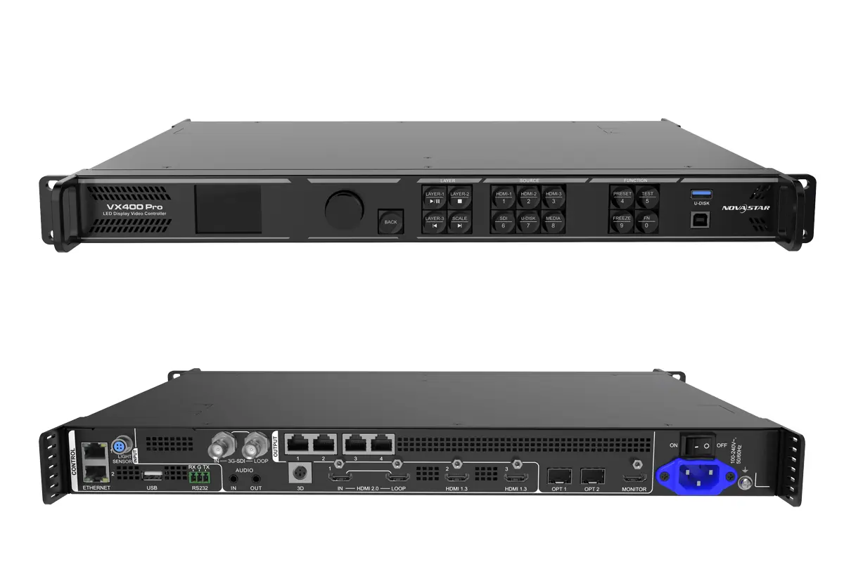
Photograph the NovaStar controller label, rear connections and current rack layout. Record the model suffix, hardware revision where available, firmware, control software version and the active operating mode. Two products with similar names may have different output arrangements. A purchasing spreadsheet copied from the original tender should be checked against what was actually installed.
For each cabinet type, record physical size, pixel width and height, module identification, receiving card model and quantity, and the path through its data connectors. Record any repaired cabinets separately. An old wall can contain several replacement batches even when every front surface looks identical. These differences matter when a NovaStar controller must serve both retained and newly supplied hardware.
Give every existing cabinet a location reference on a front-view drawing. Mark the first cabinet on each data chain and the direction through subsequent cabinets. Photograph cable labels before disturbing them. The drawing should distinguish screen coordinates from physical cable order, so a technician can understand both without relying on the installer who originally built the wall.
02. Preserve a baseline that can be restored
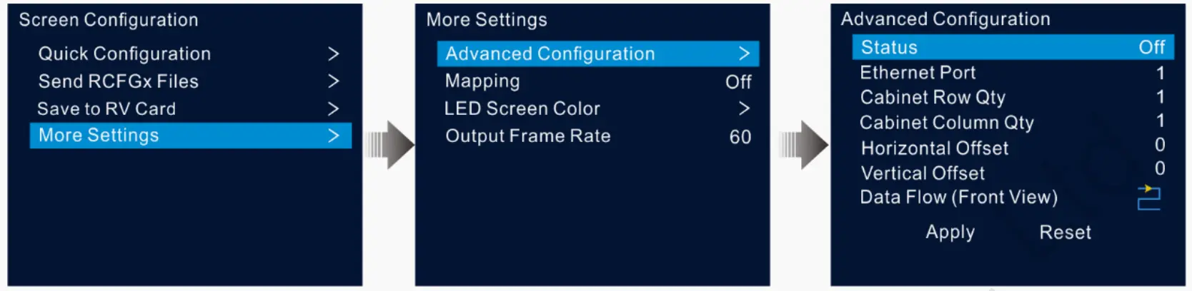
Save the current screen mapping, receiver configuration and relevant calibration material using the procedures appropriate to the installed equipment. Keep a dated copy outside the commissioning laptop. EagerLED’s NovaLCT configuration backup and restore guide explains the configuration-file workflow; the expansion record should identify which saved files belong to which hardware.
Also photograph a known test pattern on the unchanged wall. Include seams, small text and low gray content at the normal operating brightness. This is a comparison baseline, not a laboratory performance certificate. If the existing display already has a fault, document it before the NovaStar controller is reconfigured so the expansion acceptance discussion starts from an agreed condition.
2. Check Both Overall Capacity and Individual Port Loading
01. Use the specification for the actual operating conditions
A NovaStar controller needs a capacity check at two levels: the complete screen and each output path. Calculate the proposed pixel canvas from cabinet pixel dimensions, not from its width in meters. Separately verify the allowed width, height, receiver limits, frame rate, bit depth and feature mode. Passing one limit does not imply that the others pass.
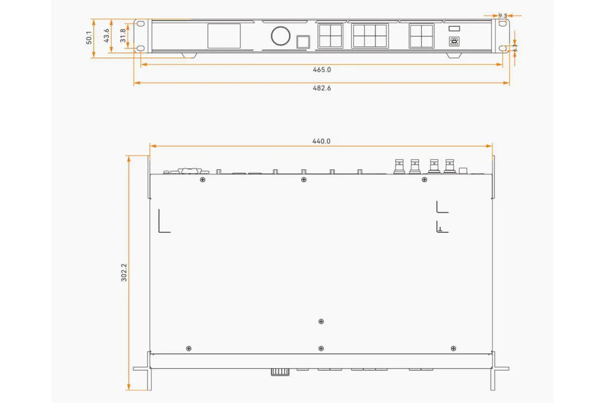
For a specific reference, NovaStar’s VX400 Pro Specifications V1.3.0, dated February 11, 2026, lists four Gigabit Ethernet outputs, a maximum device load of 2.6 million pixels and an 8-bit single-port maximum of 650,000 pixels. Its stated maximum width is 10,240 pixels and maximum height is 8,192 pixels. Those dimension limits are not permission to multiply them into a supported full screen.
The same specification describes optical output as carrying the four Ethernet outputs, with copy or backup functions. Therefore, adding an optical connection does not create four more independent output loads. These are model-specific facts; confirm the corresponding conditions for the NovaStar controller being retained and the planned receiver arrangement.
02. Check how whole cabinets fit onto ports
Consider a hypothetical cabinet with 256 by 256 pixels, or 65,536 pixels. Nine such cabinets contain 589,824 pixels. Ten contain 655,360 pixels, which exceeds the example’s stated 650,000-pixel port limit. This simple arithmetic reveals a problem that can be hidden by an acceptable total screen count.
Assume each cabinet must remain entirely on one port and that no receiver-level split has been approved. Four ports can then accommodate at most nine of these cabinets per port under this initial arithmetic check. A proposed thirty-seventh cabinet would push at least one port above that limit even though the aggregate pixels remain below 2.6 million.
| Hypothetical layout | Total active pixels | Whole-cabinet port check | Initial decision |
|---|---|---|---|
| 36 cabinets | 2,359,296 | Nine per port could fit the stated numeric limit | Continue topology and operating-condition checks; not yet approved |
| 37 cabinets | 2,424,832 | At least one port needs ten if cabinets stay whole | Redesign routing or capacity before ordering |
| 40 cabinets | 2,621,440 | Ten per port also exceeds the example limit | Both aggregate and port calculations fail |
This table is an illustrative calculation, not a recommended screen geometry. A NovaStar controller may impose additional rectangular loading or topology conditions. Empty space inside a mapped region may also affect the calculation for the selected mode. Check those conditions with the supplier rather than treating the sum of illuminated pixels as the complete approval.
Keep the calculation in the quotation file with its assumptions. If the customer later changes cabinet pitch, orientation or screen shape, recalculate it. A NovaStar controller that was suitable for the first drawing may no longer fit the revised layout even when the physical display area changes only slightly.
3. Verify New Cabinets Against the Retained Receiver System
01. Ask for a compatibility statement with named components
Send the supplier the actual receiving card models, firmware versions, module details and proposed cabinet quantities. Ask which combinations are supported and which require a change. An answer that merely says “works with NovaStar” is too broad. The NovaStar controller is one part of a chain that also includes receiver hardware, output settings and the LED modules.
For the added cabinets, request a sample configuration file tied to the supplied hardware and a record of the intended firmware. Keep the original and expansion files distinguishable. Do not broadcast an unverified receiver file across the operating wall just because the new cabinets share its pitch. Module wiring, driver configuration and receiver allocation can differ.
The supplier should explain any proposed receiver substitution before the order is released. Include its effect on mapping, calibration handling, service spares and the commissioning procedure. A NovaStar controller compatibility review should end with a named combination of parts, not a general brand-level assurance that cannot be tested on delivery.
02. Separate signal compatibility from visual matching
A working data connection does not prove that old and new cabinets will look the same. Assess the actual samples together at the intended viewing distance and brightness. Inspect white balance, low gray transitions, color fields and seams. Record the agreed observation conditions so a later disagreement is not based on photographs taken with different camera settings.
Ask whether the proposed LED display modules match the retained hardware mechanically as well as electrically. Confirm service access, connector direction and spare-part identification. If an acceptable visual match cannot be demonstrated, consider a clearly separated new display area or a broader replacement rather than assuming the NovaStar controller can correct every batch difference.
Keep calibration ownership explicit. Identify which files or coefficients will be supplied, who will apply them and what the installer can recover after a repair. Avoid promising a seamless blend from controller adjustment alone. That promise needs evidence from the real cabinets and an acceptance method suitable for the customer’s use.
4. Redesign the Canvas, Source Layout and Physical Cable Map
01. Treat added pixels as a content change
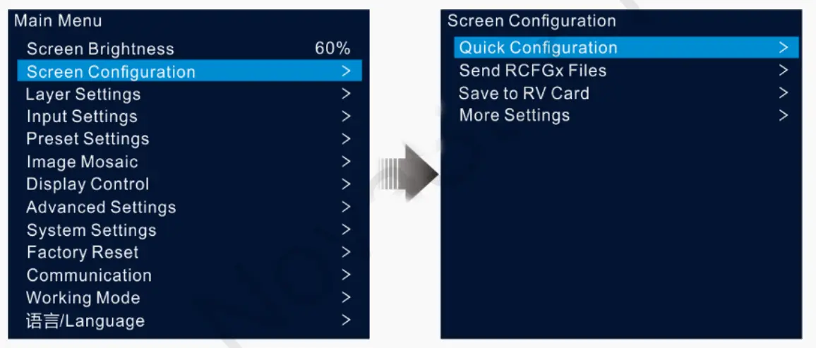
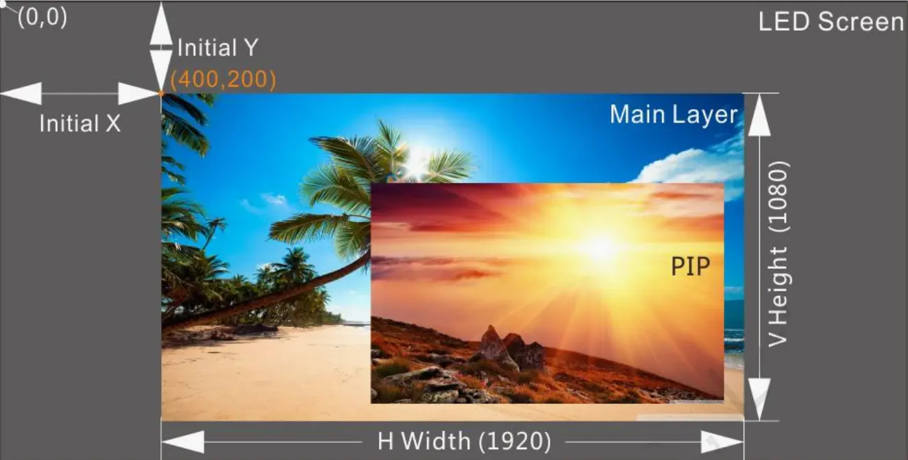
The expanded wall needs a defined native canvas and a content plan. Decide whether existing presentations will be scaled, cropped, centered with unused space, or redesigned for the new aspect ratio. A higher-resolution input connector does not itself establish the native output capacity of a NovaStar controller. Verify both sides of the signal path.
Prepare a labeled test image at the intended canvas size with edge markers and readable text in each new section. Show the content team where titles, captions and logos may appear. This catches a common handover problem: the electronics display an image correctly, but the presentation template still assumes the old screen boundaries.
Record source resolution, refresh rate, output timing and the selected processing mode together. Re-test presets that position or crop layers after the canvas changes. If a proposed NovaStar controller mode removes a processing function that the operator relies on, the extra capacity is not a complete solution. Quote the functional tradeoff explicitly.
02. Route cables for operation and maintenance
Draw the new cable order before installation. Mark retained runs, new runs, connector locations and service loops. Make sure every route can be traced without removing unrelated cabinets. A NovaStar controller port map should identify its physical cable label and the cabinet locations served, allowing a technician to diagnose a dark region from either end.
Check the rack as well as the wall. Cable bend space, connector access, ventilation and the route to any optical distribution equipment can affect the practical installation. A front-view rack drawing alone may hide an inaccessible rear connection. Include photographs or a measured section where space is tight.
If backup paths are part of the design, draw and test them separately. State what failure the arrangement is intended to cover and what remains a shared point of failure. Do not count a copied output as added image capacity. For any NovaStar controller, the approved backup behavior must be verified with the actual cabling and receiver configuration.
5. Test a Representative Expansion Before Releasing the Full Order
01. Agree on what the sample test must prove
Use the retained NovaStar controller, a representative existing cabinet and the proposed new cabinet wherever practical. A test using only new equipment does not demonstrate the old-to-new interface. Record serial or batch references, settings and the exact test arrangement so the result can be reproduced during site commissioning.
Begin with an isolated setup that cannot overwrite the operating wall. Check identification, receiver communication and a labeled pixel map before loading the customer’s content. Then inspect the joint between old and new cabinets. Keep failed observations in the record, including the change that resolved each one, rather than recording only the final successful photograph.
| Acceptance item | Evidence to retain | Decision owner |
|---|---|---|
| Cabinet identity and configuration | Labels, receiver versions and file references matching the proposed order | Integrator with supplier |
| Expanded pixel mapping | Front-view map and test image reaching every intended region correctly | Commissioning technician |
| Old-to-new visual transition | Agreed viewing conditions and customer observation of representative content | Customer’s display representative |
| Normal restart and recovery | Recorded restart sequence and verified retained settings | Site operator with integrator |
| Backup behavior, if included | Controlled failure test and observed effect on the display | System designer and technician |
Agree on acceptance criteria before the demonstration, including who can accept an unresolved limitation. “Looks fine” without a named observer or test content is a weak purchasing record. A NovaStar controller sample test should give procurement a clear pass, a conditional pass with listed changes, or a stop decision.
02. Include restart and operator behavior
After saving the approved settings, perform a planned restart in the test arrangement and confirm the screen returns as intended. Load the presets the operator actually uses. Check source switching and the normal startup order. A single uninterrupted image does not prove that the expanded system will recover correctly after routine shutdown.
Set the demonstration length and content sequence to reflect the intended application. Do not convert a short bench test into a claim about long-term reliability. If an issue requires firmware or hardware changes, record a new test configuration. The NovaStar controller approval should refer to the final tested combination, not an earlier version of the proposal.
6. Price the Complete Change and Keep a Recovery Route
Compare retention and replacement on total work scope. Retaining a NovaStar controller may reduce equipment purchases while increasing remapping, cable work or testing. A replacement may require new operating presets, spare parts and staff familiarization. Put these items on separate quotation lines so the customer can see what each option includes.
For the change window, identify the last point at which the original wall can be restored within the available time. Keep original files and removed components identifiable. Assign one person to authorize the return to the baseline if the expansion fails acceptance. This is a practical installation decision, not a reason to experiment with unverified firmware during normal operation.
At handover, deliver the final cabinet drawing, output map, file versions, equipment inventory and accepted limitations together. Update labels at the NovaStar controller and on accessible cable ends. Show the site operator where the recovery files are stored and which supplier to contact for a replacement receiver or module.
FAQ
Can I reserve capacity for a later second expansion?
Yes, but define that future layout separately. Ask for both today’s approved map and a provisional future calculation, including the likely receiver arrangement and source canvas. Spare aggregate pixels alone do not guarantee usable port distribution. Keep the future design marked provisional until its exact cabinets and operating conditions are known.
What if the original installer cannot supply configuration files?
Ask a qualified technician to inspect the operating system and determine what can be read back with the appropriate software. Preserve the current behavior before making changes. If a reliable baseline cannot be established, include investigation and recovery work in the scope instead of treating the expansion as a routine cabinet addition.
Can a rental cabinet temporarily replace an added cabinet?
Only after its mechanical fit, receiver configuration, pixel dimensions and visual behavior have been checked for that installation. Similar pitch or external size is insufficient. Keep temporary equipment identified in the handover record and explain any limitations to the operator before using it in a customer-facing display.
Should a spare controller use the expanded configuration?
The spare NovaStar controller should have a documented recovery procedure for the accepted system. Verify its exact hardware and firmware compatibility and test the intended substitution. Keep the pre-expansion baseline archived separately so an operator does not accidentally restore an obsolete screen map while attempting a repair.
What should be checked when expansion changes the screen’s orientation?
Review cabinet mounting suitability, pixel mapping, content orientation and service access together. A rotated physical arrangement is not just a different slide template. Have the supplier confirm the intended installation and have the integrator test readable content, cabinet order and maintenance access before approving that change.
Prepare an Expansion Review
Send the current cabinet map, receiver inventory, saved configuration references and proposed expansion drawing for review. Include the operating resolution, frame rate, content sources and available installation window. These details make a NovaStar controller assessment specific enough to support an equipment decision.
Use the VX400Pro product reference when that is the model under consideration, and contact EagerLED with the expansion details for a configuration and equipment discussion. Ask for written assumptions and a representative test plan before purchasing the additional cabinets.