

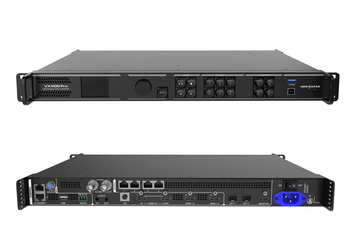
The NovaStar VX400 Pro is an all-in-one LED display controller with four Gigabit Ethernet outputs and a total loading capacity of 2.6 million pixels. Its HDMI 2.0 input accepts up to 4096 × 2160 at 60 Hz, it provides six 2K × 1K layer resources, and ByPass mode can reduce device latency to 0 frames. This guide brings the official manual, specifications, firmware links, setup workflow, capacity limits and troubleshooting notes into one place.
NovaStar also writes the model as VX400 Pro; searches for VX400Pro refer to the same controller. The technical values below were checked against NovaStar’s official VX400 Pro Specifications V1.3.0 and VX Pro Series User Manual V1.3.1.
- Loading capacity: 2.6 million pixels across 4 Gigabit Ethernet ports
- Maximum canvas: 10,240 pixels wide or 8,192 pixels high
- Maximum HDMI 2.0 input: 4096 × 2160@60Hz
- Layers: 6 × 2K × 1K layer resources
- Latency: 1-2 frames in low-latency Video Controller mode; 0 frames in ByPass mode
- Control: front panel, NovaLCT, Unico client/web and VICP app
1. NovaStar VX400 Pro Overview and Specifications
The VX400 Pro combines video processing, LED sending control and fiber conversion in a 1U controller. It supports three operating modes: Video Controller, Fiber Converter and ByPass. This makes it suitable for rental stages, control rooms, conference displays, fine-pitch LED walls and unusually wide or tall screen layouts.
Key VX400 Pro Specifications
| Specification | Official value | Planning note |
|---|---|---|
| Total loading capacity | 2.6 million pixels | Shared by 4 Gigabit Ethernet outputs |
| Maximum output dimensions | 10,240 px wide / 8,192 px high | Total pixel count must still remain within 2.6 million |
| HDMI 2.0 input | Up to 4096 × 2160@60Hz | Supports 8-bit, 10-bit and 12-bit video inputs |
| HDMI 1.3 inputs | 2 inputs, up to 1920 × 1080@60Hz | Custom width or height up to 2048 pixels |
| 3G-SDI input | Up to 1920 × 1080@60Hz | Includes 3G-SDI loop output |
| Layer resources | 6 × 2K × 1K | Higher-resolution layers consume multiple resources |
| Ethernet outputs | 4 × Gigabit Ethernet | Up to 650,000 pixels per port at 8-bit output |
| Optical ports | 2 × 10G optical ports | OPT 1 is adaptive input/output; OPT 2 supports copy, backup or loop |
| Presets | Up to 256 | Save repeatable stage or screen layouts |
| Certifications listed by NovaStar | CE, FCC, IC, PSE, RCM, EAC, UL, CB, KC and RoHS | Confirm the certification required for the destination market |
Source: NovaStar VX400 Pro official product page and the official Specifications V1.3.0.
2. Official VX400 Pro Manual, Specifications, Software and Firmware
Use NovaStar’s current files rather than third-party copies. The official downloads checked while updating this guide are:
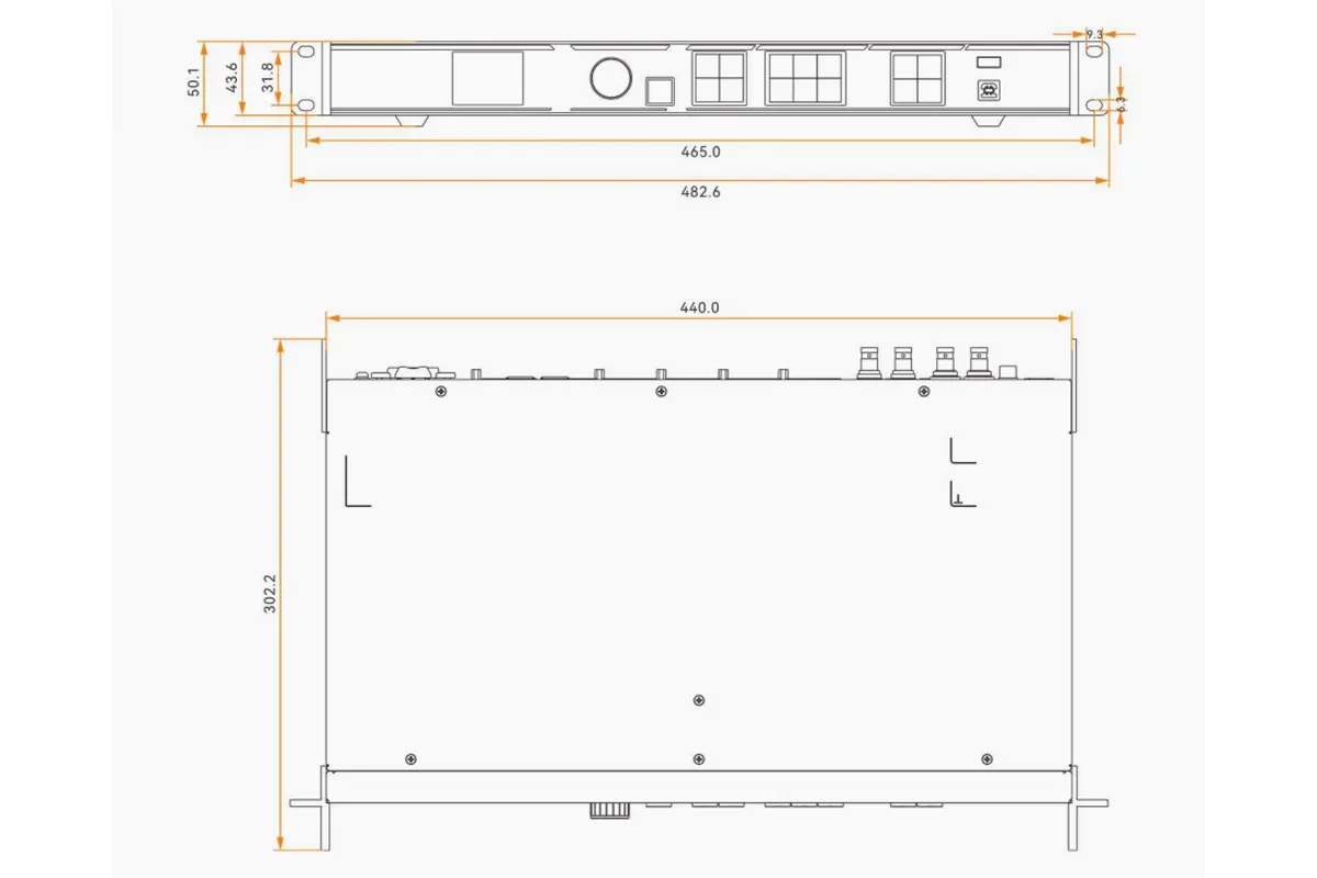
- VX400 Pro All-in-One Controller Specifications V1.3.0 (PDF) – connector limits, latency, dimensions, electrical requirements and supported formats.
- VX Pro Series All-in-One Controller User Manual V1.3.1 (PDF) – screen configuration, input settings, layers, backup, OSD and troubleshooting.
- VX Pro Series Quick Start Guide V1.0.1 (PDF) – initial cabling and commissioning reference.
- VX400 Pro firmware V1.3.1 (ZIP) – verify the model and installed version before upgrading; do not interrupt power during an update.
For screen configuration, download NovaLCT software. The VX400 Pro can also be managed with the Unico client or web interface and the VICP app. Check the official product page before installation because NovaStar may publish newer files.
3. Loading Capacity and Suitable Applications
The 10,240 × 8,192 figure describes the maximum width and height boundaries, not a canvas containing that many pixels. The configured screen must remain within the controller’s 2.6-million-pixel total capacity. At 8-bit output, each Ethernet port supports up to 650,000 pixels.
| Project requirement | VX400 Pro fit | What to verify |
|---|---|---|
| Small-to-medium LED wall | Strong fit | Total pixels and per-port cabinet loading |
| Ultra-wide ticker or ribbon | Supported up to 10,240 px wide | Total pixels remain below 2.6 million |
| Ultra-tall screen | Supported up to 8,192 px high | Topology, receiving-card compatibility and port loading |
| Live stage or camera workflow | Low-latency and ByPass options | Processing requirements, sync source and redundancy |
| Long-distance fiber link | OPT copy/backup/loop modes | Optical modules are purchased separately |
| Large wall above 2.6 million pixels | Use a larger controller or multiple-device design | Compare the NovaStar H Series and VX Series |
NovaStar specifies transmission distances of up to 10 km with a single-mode twin-core optical module and up to 300 m with a multi-mode twin-core module. These distances depend on using the specified optical modules and correct fiber infrastructure.
Important 3D limit: when 3D is enabled with Side-by-Side or Top-and-Bottom input, the device output capacity is halved.
4. Step-by-Step NovaStar VX400 Pro Setup
Step 1: Cable the signal, control and LED outputs
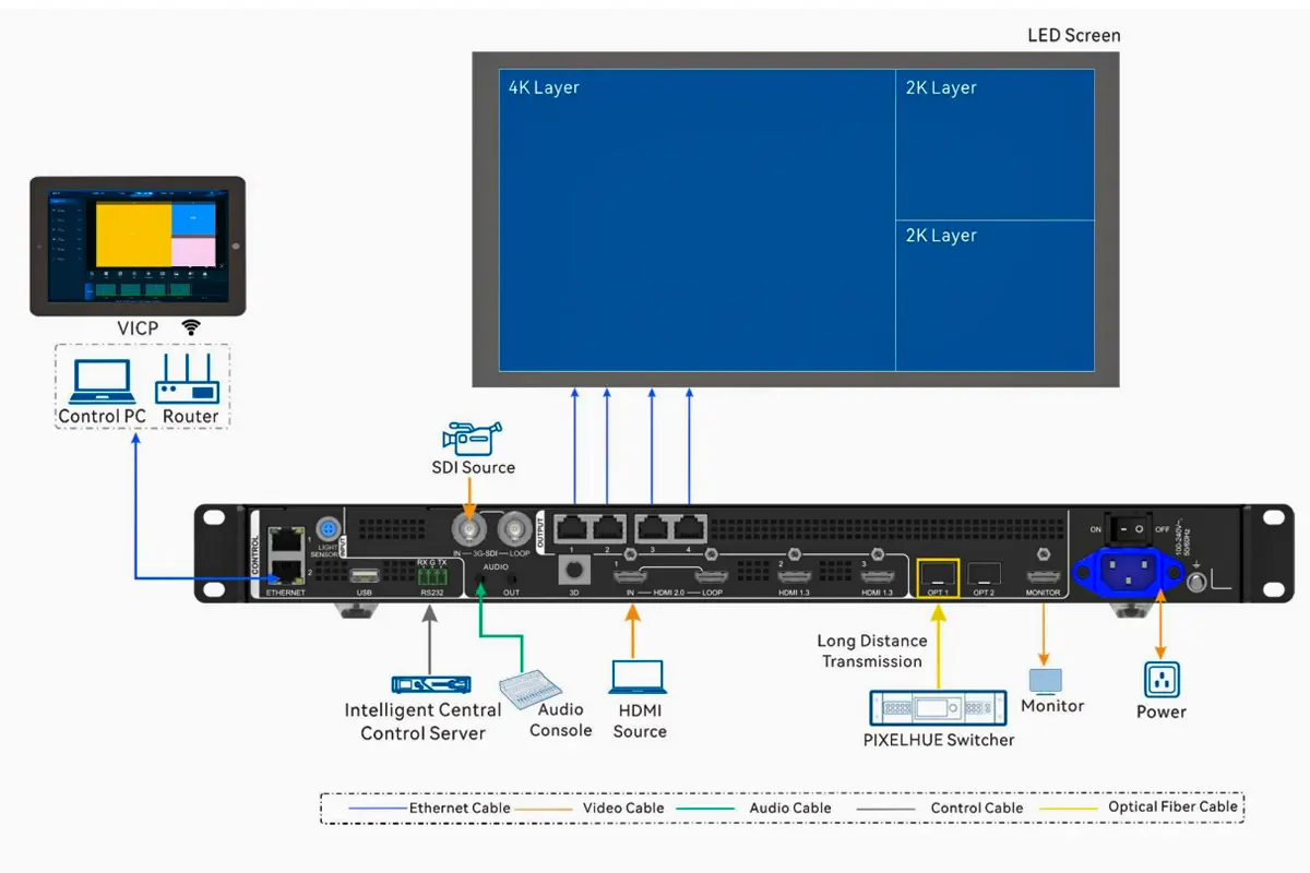
- Connect the video source to HDMI 2.0, HDMI 1.3, 3G-SDI or OPT 1 as required.
- Connect Ethernet outputs 1-4 to the receiving cards in the LED cabinets using the planned topology.
- Connect a control computer through USB or Ethernet when using NovaLCT or Unico.
- Use the HDMI 1.3 monitoring output if a local confidence monitor is required.
- Power the system according to the project’s electrical and signal sequence.
Step 2: Confirm software and device status
Confirm the model, current firmware and network connection before changing settings. Use firmware intended specifically for the VX400 Pro. Save the existing configuration before an upgrade or major change.
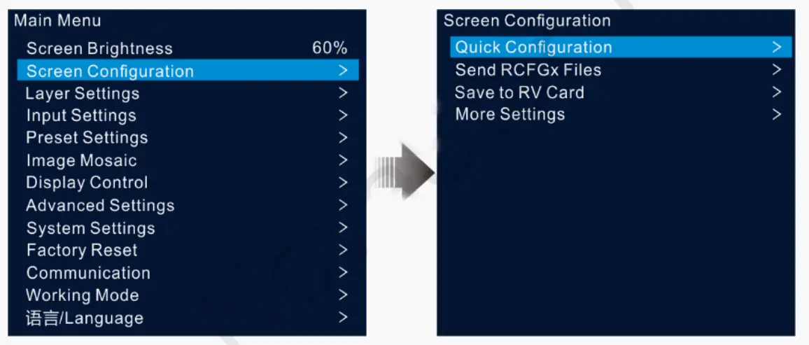
Step 3: Configure the LED screen
- Open NovaLCT or Unico and select the connected VX400 Pro.
- Load the correct receiving-card configuration file for the cabinets.
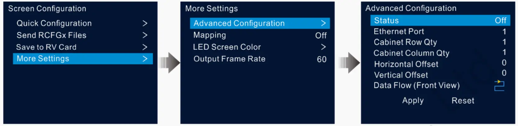
- Set the screen canvas to match the physical LED resolution.
- Map cabinets to Ethernet ports in the same order as the physical data cables.
- Use Match Screen or the equivalent canvas function, then verify the topology with mapping and test patterns.
- Save the completed screen configuration and a restorable backup.
The official manual notes that Unico or NovaLCT can be used for screen configuration. A saved screen configuration can be exported as an .scr file, while receiving-card parameters normally use an .rcfgx file.
Step 4: Configure input and output
Select the input source, confirm its detected resolution and set connector capacity when necessary. Choose the correct scaling mode: full screen, pixel-to-pixel or custom. Set the sync source when several controllers or processors must remain synchronized.
Step 5: Test before content playback
Run test patterns to check cabinet order, color channels, dead pixels and visible seams. Verify primary and backup inputs, Ethernet backup, optical backup and saved presets before the display is handed over for live use.
5. Inputs, Layers and Output Configuration
Choose the correct input capacity
| Capacity mode | Standard resolution examples | Custom boundary |
|---|---|---|
| SL | 1920 × 1080@60Hz | Up to 2048 px width or height at the documented timing |
| DL | 3840 × 1080@60Hz or 3840 × 2160@30Hz | Up to 4096 px width or 3840 px height at the documented timing |
| 4K | 4096 × 2160@60Hz or 8192 × 2160@30Hz | Up to 8192 px width or 8188 px height at the documented timing |
If an input is larger than the selected connector capacity, the source may not be processed correctly. Change the capacity setting before troubleshooting the LED cabinets.
Understand the six layer resources
The VX400 Pro provides six 2K × 1K layer resources. This does not always mean six 4K layers:
- A 2K × 1K layer uses 1 resource.
- A 4K × 1K layer uses 2 resources.
- A 4K × 2K layer uses 4 resources.
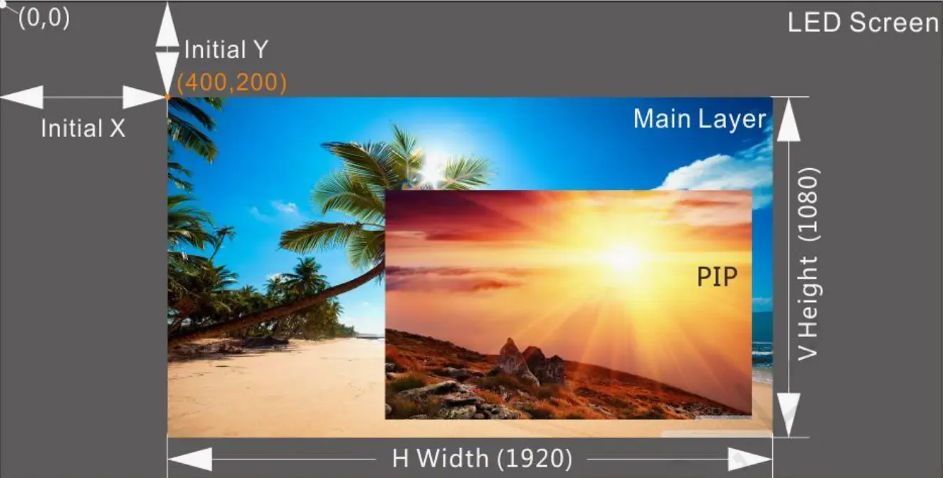
Layer size, position, priority and aspect ratio are adjustable. Use input cropping when only part of a source should appear, and remember that the total layer-resource budget still applies.
Output and monitoring options
- Ethernet 1-4: LED data output, up to 2.6 million pixels total.
- OPT 1: adaptive optical input or sending-card output.
- OPT 2: output copy, backup or optical loop.
- HDMI 1.3 output: fixed 1920 × 1080@60Hz monitoring output.
- Audio: HDMI embedded audio plus independent 3.5 mm input and output.
6. Low Latency, Backup and Reliability
| Working mode | Low-latency setting | Normal setting |
|---|---|---|
| Video Controller | 1-2 frames | 2-3 frames |
| ByPass | 0 frames | 1 frame |
| Fiber Converter | 0 frames | 0 frames |
These are device latency values from NovaStar’s official specification. ByPass reaches 0 frames because video processing is unavailable in that mode. If scaling, cropping or layers are required, use Video Controller mode and plan for its processing delay.
In Auto low-latency mode, the controller checks the screen topology. Cabinets on each Ethernet port must not overlap; their bounding rectangles must align at the top of the canvas. Free-topology layouts have additional requirements, including consistent cabinet size and a maximum 650,000-pixel bounding rectangle per port. Manual low-latency mode can reduce effective port capacity if cabinet coordinates begin below the top of the canvas.
For live or mission-critical displays, configure more than one level of protection where appropriate:
- Primary and backup input sources
- Backup between Ethernet ports
- OPT and Ethernet output backup
- Backup between controllers
- Dual receiving-card backup where supported
- Saved presets and restore points
The V1.3.0 specification supports up to five restore points with a combined 1 GB limit.
7. VX400 Pro Troubleshooting Checklist
| Symptom | Checks |
|---|---|
| No image or a black screen | Confirm the selected input, source signal, connector-capacity mode and HDCP setting. HDMI inputs do not support interlaced signals. |
| Image is cropped or offset | Match the canvas to the physical resolution, verify cabinet coordinates and check the scaling mode. |
| Some cabinets are missing | Check Ethernet-port loading, cable order, receiving-card file and topology mapping. |
| Low latency will not enable automatically | Check for overlapping cabinets, Y-axis offsets, inconsistent cabinet sizes and per-port pixel limits. |
| OPT backup does not switch correctly | Confirm OPT 2 is set to Backup rather than Copy and test the stored backup configuration before the event. |
| USB media will not play | Use one NTFS, FAT32 or exFAT partition and a supported codec. The VX400 Pro USB source output is fixed at 1920 × 1080@60Hz. |
When troubleshooting continues, record the firmware version, input format, canvas dimensions, cabinet topology and the exact error message before contacting support. This information makes remote diagnosis substantially faster.
8. NovaStar VX400 Pro FAQ
Where can I download the official NovaStar VX400 Pro manual?
Download the current VX Pro Series All-in-One Controller User Manual from the NovaStar VX400 Pro product page. The official version checked for this guide is V1.3.1. A direct PDF link is provided in the downloads section above.
What is the maximum loading capacity of the NovaStar VX400 Pro?
The VX400 Pro loads up to 2.6 million pixels through four Gigabit Ethernet outputs. The maximum canvas width is 10,240 pixels and the maximum height is 8,192 pixels. At 8-bit output, each Ethernet port supports up to 650,000 pixels.
Does the NovaStar VX400 Pro support 4K at 60 Hz?
Yes. Its HDMI 2.0 input supports up to 4096 × 2160@60Hz. The two HDMI 1.3 inputs and the 3G-SDI input support up to 1920 × 1080@60Hz.
Which software works with the NovaStar VX400 Pro?
The VX400 Pro can be controlled from its front panel, NovaLCT, the Unico client or web interface, and the VICP app. Use NovaStar’s current software and firmware for the installed device version.
How many layers does the VX400 Pro support?
The VX400 Pro provides six 2K × 1K layer resources. A 4K × 2K layer uses four resources, a 4K × 1K layer uses two, and a 2K × 1K layer uses one.
Can the VX400 Pro achieve zero-frame latency?
Zero-frame latency is available in ByPass mode. Low-latency Video Controller mode is rated at 1-2 frames, while normal Video Controller mode is rated at 2-3 frames.
Is the VX400 Pro an outdoor-rated controller?
The VX400 Pro is an indoor controller and should be installed in a protected, ventilated equipment rack. Outdoor suitability depends on the LED cabinets and enclosure, not on the controller alone.
Need help matching the controller to an LED wall? Send EagerLED the screen width, height, pixel pitch, cabinet resolution, input format and required backup level. We can calculate the controller load and recommend a practical system architecture before quotation.
For related tools, see the NovaLCT download guide and NovaStar LED control software resources.