

COB LED display repair can involve correcting a power or signal fault, replacing a damaged module, or sending an assembly to a specialist repair facility. A defective pixel does not automatically require a new video wall. The appropriate route depends on the failed component, the module construction, compatible spare parts, and the supplier's supported service process.
For an AV integrator, restoring an image is only part of the job. The repaired area must fit correctly, reproduce the surrounding image, retain its settings after restart, and remain serviceable. A replacement that lights up but leaves a visible rectangle may still fail the customer's acceptance requirements.
Planning COB LED display repair before purchasing the screen helps avoid that situation. This guide connects fault diagnosis with module identification, replacement decisions, calibration, and service costs. It covers direct-view RGB video walls, rather than COB lighting strips, projector light sources, or television backlights.
1. What Can Be Repaired in a COB LED Display?
COB means chip on board. In a direct-view display, bare LED dies are mounted on a circuit board and protected by encapsulation. The screen also contains driver electronics, power supplies, receiving cards, connectors, and a supporting structure. A fault anywhere in this system can produce a visible defect.
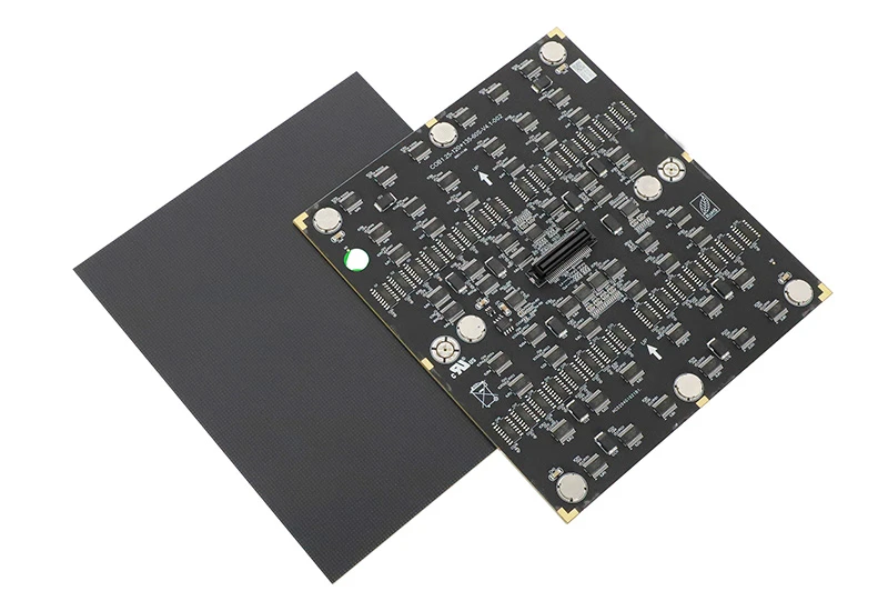
COB LED display repair therefore begins by identifying the serviceable assembly. A module is an emitting board; a cabinet holds modules and associated hardware; the complete wall combines cabinets with the control system. Suppliers sometimes use “panel” for different assemblies, so request a photograph or part drawing with every quotation.
01. Separate the emitting surface from supporting electronics
A failed power supply does not require replacing healthy LED dies. A configuration error does not become a hardware defect because it affects a large area. Conversely, changing controller settings cannot physically restore a cracked board or damaged encapsulation.
The sealed face changes access to the emitters. Individual-die work, where the manufacturer supports it, requires a qualified process suited to that construction. An SMD lamp replacement tutorial is not an appropriate procedure for opening a COB surface. EagerLED's COB display guide explains the broader technology and purchasing considerations.
02. Define what a successful repair must achieve
Set the target for COB LED display repair before ordering parts: electrical operation, mechanical fit, acceptable appearance, and documented settings. For a boardroom, an uneven gray presentation background may matter more than its appearance in a bright promotional video.
COB LED display repair should also leave a clear service history. Record the removed and installed serial numbers, the location, and any configuration changes. That record makes a recurring fault easier to distinguish from a new problem.
2. Diagnose the Fault Before Replacing a Module
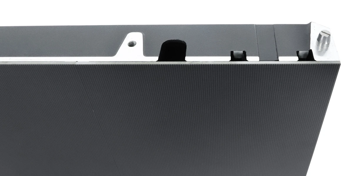
Start COB LED display repair with observations that narrow the fault location. Photograph the complete wall and the affected area. Note whether the defect appears immediately, develops after warm-up, follows particular content, or began after maintenance. Preserve the original configuration before changing settings.
Use approved internal test patterns, where available, to compare the display with the normal source disconnected from the test path. A fault that disappears during an internal pattern may originate upstream of the point generating that pattern. This result narrows the search; it does not prove every downstream component is healthy.
| Observed symptom | Investigate first | Evidence that helps separate causes |
|---|---|---|
| One dark or incorrectly colored point | Individual emitter, local connection, or drive channel | Close-up images on separate red, green, and blue patterns |
| A complete module is black | Local power, data connection, interface, or module electronics | Exact module boundary and comparison with adjacent modules |
| Several cabinets fail together | Shared power or upstream signal path | Cabinet map, connection order, and controller status |
| A repeated line or block is wrong | Driver, data path, scan configuration, or board fault | Pattern location and whether it persists across test sources |
| One replacement area is brighter | Calibration, settings, batch differences, or installation | Uniform gray fields at the normal operating brightness |
| Failure appears after warm-up | Thermal conditions, power stability, or an intermittent connection | Time to onset, room conditions, load, and alarm history |
| A mark remains visible with power off | Surface contamination, damage, or mechanical alignment | Inspection under room light without pressing the surface |
The table guides investigation; none of these patterns identifies a failed part with certainty. In COB LED display repair, a rectangular fault is useful evidence because it may follow module boundaries, but the cause can still sit behind the module.
01. Change one variable at a time
A technician may substitute a verified compatible part under the manufacturer's procedure. If the symptom follows the removed module, that supports a module-level fault. If it remains at the same position, investigate the local interface, power, and signal path.
Do not connect a healthy spare to a position with suspected incorrect voltage, a short, or connector damage. Verify the electrical condition first. Otherwise, the substitution can damage the spare and make the diagnosis less clear.
02. Record intermittent behavior before resetting
Repeated restarts can temporarily hide a fault. Retain alarm messages, photos, operating settings, and the sequence of events before resetting equipment. A short phone video can document visible behavior, but camera exposure may create bands that viewers do not see.
For COB LED display repair requests involving flicker, report separately what is visible to the eye and what appears only on camera. Do not describe every recorded stripe as a damaged pixel row.
3. Information Needed for COB LED Display Repair
A useful COB LED display repair request identifies the installed hardware and the conditions of failure. “P1.25 indoor screen” is insufficient: pixel pitch describes spacing, not a complete spare-part specification.
Photograph labels before removing anything. Include both the cabinet reference and the module reference when accessible. If the supplier requests internal photographs, arrange access through a qualified technician and follow the equipment's isolation procedure.
| Information to provide | Include | Decision it supports |
|---|---|---|
| Equipment identity | Model, serial number, order reference, module revision | Identifying the original build and supported parts |
| Fault location | Cabinet row and column, module position, affected area | Separating local and shared failures |
| Visual evidence | Whole-wall view, close-up, test-pattern images | Evaluating pixel, surface, and uniformity problems |
| Operating conditions | Brightness setting, content, warm-up behavior, environment | Reproducing an intermittent symptom |
| Control information | Processor, receiving card, software and firmware versions | Checking configuration compatibility |
| Previous intervention | Parts replaced, files loaded, cleaning or physical incident | Avoiding repeated or misleading tests |
| Site constraints | Access method, permitted shutdown, destination, deadline | Planning attendance, freight, and temporary arrangements |
Keep configuration backups separate from photographs. Mapping files, receiving-card parameters, and calibration data serve different purposes; one export may not contain them all. Ask the supplier which files belong to the installed system and how they can be restored.
A COB LED display repair record should distinguish confirmed findings from assumptions. Write “the lower-left module stays black on all available test patterns,” rather than “the COB chip is burned,” unless inspection has established that cause.
When requesting remote assistance, send only the project material required for diagnosis and use your organization's approved access method. A supplier can often identify missing information from photographs, but some faults still require measurements or examination of the assembly.
4. Compare Module Replacement and Specialist Repair
The practical COB LED display repair decision concerns both restoration time and the eventual disposition of the failed part. You can install a compatible spare to return the wall to service, then send the removed module for evaluation. These actions are complementary.
| Service route | Suitable situation | Benefit | Limitation to confirm |
|---|---|---|---|
| Correct power, data, or settings | Diagnosis identifies a fault outside the emitting assembly | Retains healthy modules | Requires evidence that the original cause is resolved |
| Replace the complete module | A compatible spare exists and the module is defective | Moves detailed repair away from the installation | Fit, calibration, and visual matching still need approval |
| Specialist module repair | The manufacturer supports repair for that construction and damage | May recover a useful spare | Repairability, appearance, testing, and turnaround vary |
| Replace a cabinet assembly | Damage extends beyond one module or the service design requires it | Replaces the affected assembly together | More hardware may be exchanged than strictly failed |
| Renew a larger section or wall | Compatible parts are unavailable or condition is broadly unacceptable | Addresses wider obsolescence or damage | Requires a separate engineering and lifecycle-cost assessment |
01. When a module swap is the practical choice
For a room with a short service window, COB LED display repair may prioritize module replacement because detailed investigation can happen elsewhere. This only works if the spare is ready, accessible, and verified. “We stock a similar module” is weaker evidence than a documented compatible part tested with the delivered wall.
Keep the removed assembly labeled and protected. A repair facility may need it intact to determine whether the failure originated in the emitters, board, driver circuitry, or interface.
02. When specialist repair needs closer evaluation
Ask what “repairable” means for the proposed product. Does it cover driver components, connectors, individual emitters, surface restoration, or only an exchange service? Request the acceptance tests and any warranty applying to the returned assembly.
COB LED display repair at component level can be inappropriate when access would damage surrounding structures or the resulting surface cannot meet the project's visual requirements. The repair facility must assess that specific assembly; a universal statement about all COB products is unreliable.
An isolated failure alone is not evidence that the whole wall needs replacement. Consider broader renewal when repeated faults, unavailable parts, or unacceptable matching prevent an economical, supportable result.
5. How to Match a Replacement COB LED Module
Successful COB LED display repair requires mechanical, electrical, control, and optical compatibility. Matching dimensions and nominal pitch only addresses part of that list.
Mechanically, verify mounting positions, thickness, orientation, connector alignment, and retention method. A module that fits the opening but stands proud of its neighbors can create visible boundaries and handling risks. Confirm that it is intended for the cabinet revision on site.
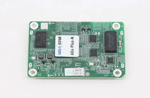
Electrically, compare the specified supply, connector pinout, power requirements, and interface. Do not treat a matching connector shell as proof of matching wiring. Control compatibility also includes pixel resolution, drive arrangement, scan configuration, receiving-card support, and the correct parameter file.
Optical matching depends on more than turning the new board to the same brightness. Emitter characteristics, surface appearance, calibration, and the operating history of adjacent modules can affect the result. Prefer documented matching spares, while still testing their appearance in the assembled screen.
For COB LED display repair involving discontinued hardware, obtain written confirmation of any substitute part. Ask whether it requires different settings, an interface change, or replacement of adjacent modules. A substitute that forces extensive changes may no longer be a simple maintenance purchase.
EagerLED's COB LED module range provides a starting point for discussing parts. Send the existing module label and front-and-rear photographs before requesting a replacement quotation; a product-category listing is not a compatibility approval.
6. Plan Safe Removal and Reinstallation
COB LED display repair on site should follow the exact product's service instructions. Front access describes an access direction; it does not establish which tool, lifting force, or connection sequence is appropriate.
01. Prepare the work area and isolate the equipment
Agree the outage with the room operator. Preserve settings, mark the module location, clear the work area, and prepare a protected surface for the removed part. Qualified personnel should isolate the relevant power sources and verify the condition required by the manufacturer's procedure.
Use the specified electrostatic-discharge controls and handling method. Do not press on the emitting face, pry against adjacent modules, or assume a generic suction cup is suitable. EagerLED's COB/GOB front-service tool overview illustrates a product-specific tool category; suitability still needs confirmation for the installed screen.
02. Inspect the position before fitting the spare
During COB LED display repair, inspect accessible mounting points and interfaces for deformation, contamination, loose retention, and damaged connectors. Resolve any verified supply or interface fault before reconnecting a replacement. Preserve evidence of physical damage for the service record.
Support the assembly during extraction and installation. Align the prescribed locating features and avoid forcing connectors. Check the finished face for level and gaps before restoring power according to the documented sequence.
03. Restore operation without changing unrelated settings
Apply only the verified files and adjustments required by the replacement. Avoid simultaneous firmware upgrades or broad parameter changes unless the supplier's procedure requires them. Too many changes make it difficult to explain a new symptom or return to the previous working state.
Treat COB LED display repair as incomplete until the screen passes functional and visual checks. Retain the failed module for the agreed return process, and mark any spare removed from stock so inventory remains accurate.
7. Check Calibration and Image Quality After Repair
COB LED display repair is not finished when the first image appears. Check whether the replacement matches the wall under the conditions the customer actually uses, including low brightness and ordinary room lighting.
01. Separate configuration from calibration
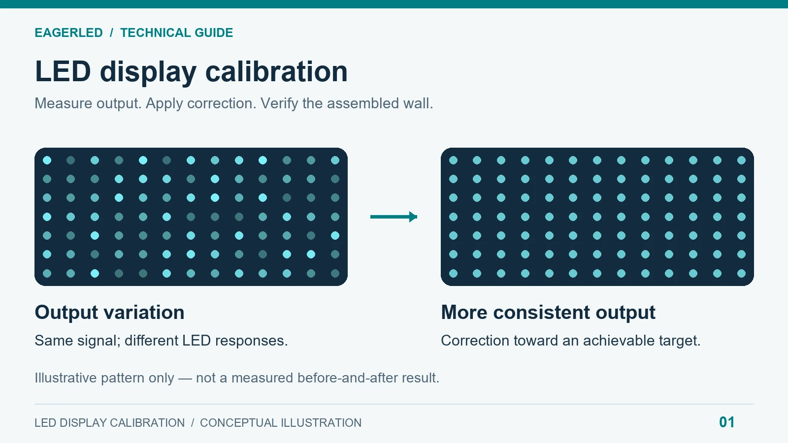
Configuration controls how the hardware receives and drives the image. Calibration applies measured corrections to improve output consistency. Restoring a receiving-card configuration does not necessarily restore the correct calibration data.
Some control systems can manage coefficients stored in module flash, provided the module and receiving hardware support that function. NovaStar's NovaLCT documentation describes these operations, with availability dependent on the hardware and software. Follow the instructions for the installed combination rather than applying a remembered menu sequence.
After COB LED display repair, verify that any restored coefficients correspond to the replacement hardware and its actual location. Do not indiscriminately copy a neighboring module's correction data onto a different board. Save the verified result and check persistence after a controlled restart.
02. Test appearance beyond a bright white screen
| Check | What to examine | Evidence to retain |
|---|---|---|
| Separate primary colors | Missing channels, wrong colors, isolated points | Pattern name and close-up images |
| Gray fields at several levels | Visible rectangles, tint shifts, low-level unevenness | Brightness setting, room conditions, and observations |
| Black image and powered-off surface | Stuck emission versus reflection or surface damage | Separate powered and unpowered observations |
| Fine text and grid pattern | Mapping, orientation, missing lines, alignment | Source resolution and displayed pattern |
| Normal project content | Readability and appearance at real viewing positions | Customer-approved content and viewing locations |
| Warm operation | Recurrence, instability, or alarms under the agreed load | Operating duration, settings, and event record |
| Controlled restart | Retention of mapping, brightness, and calibration | Restart result and saved file versions |
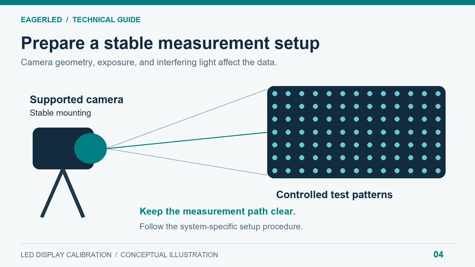
For a camera-facing wall, add the production camera, lens, frame rate, shutter, and brightness combination to acceptance. A phone recording is useful supporting evidence, but it is not a substitute for instrumented measurements where the contract requires them.
Calibration also has limits. It cannot remove a scratch, correct a warped mounting plane, or make every mismatched module optically identical. If the target exceeds what the combined hardware can reproduce, review the part selection and agreed acceptance criteria.
The LED display calibration guide explains the distinction between brightness and color correction. Specify the required test method before COB LED display repair begins, so the integrator and customer evaluate the same result.
8. Budget for Repair and Prepare Spare Parts
The cost of COB LED display repair includes diagnosis, parts, labor, access, freight, calibration, testing, and disruption. A low module price can be misleading if the quote excludes removal, return shipping, or the work needed to restore visual consistency.
Compare quotations using the same scope. Ask separately about a replacement part, repair of the failed assembly, and any temporary service arrangement. Response time, replacement dispatch, and confirmed restoration are different commitments.
| Cost or service item | Question to resolve |
|---|---|
| Diagnosis | Is assessment included, and what happens if repair is declined? |
| Replacement parts | Is the quoted part new, repaired, or an exchange unit? |
| Attendance and access | Who supplies technicians, lifting equipment, and site permits? |
| Calibration and acceptance | Are matching, testing, and a documented restart included? |
| Freight and returns | Who pays each shipping leg and handles damaged-on-arrival claims? |
| Timing | Does the commitment cover response, dispatch, or restoration? |
| Warranty | Which failure types, labor items, and repaired parts are covered? |
A practical COB LED display repair reserve contains more than boards. Keep verified spare modules, required tools, current configuration backups, and identification records available to the service team. Set spare quantities according to the installed module population, replenishment time, operating importance, and supported service route. There is no single percentage appropriate for every project.
Store spares under their specified conditions and inspect them through an agreed maintenance process. A sealed carton on a shelf does not prove that the enclosed part remains ready for use. Record each withdrawal, return, and replacement purchase.
Plan COB LED display repair with the same team responsible for ongoing maintenance. Use the site-specific maintenance planning guide to connect access, inspections, and escalation responsibilities. Before handover, demonstrate that the people responsible for the wall can locate the spares, identify the correct files, and reach the agreed service contact.
9. FAQ
01. Can a scratched COB surface be polished or recoated on site?
Do not assume it can. Abrasion, solvents, or an unapproved coating may change reflection, color, and protection or cause further damage. Photograph the mark under room light and during operation, then request the manufacturer's assessment. If a cosmetic repair is offered, ask how its appearance and durability will be checked against the surrounding surface.
02. Does one dead pixel qualify for a warranty repair?
That depends on the written warranty and acceptance criteria. Confirm whether limits refer to pixels or individual color emitters, how clusters are treated, and what viewing and test conditions apply. COB LED display repair eligibility should be established from the supplied product's terms, rather than inferred from a general statement that the screen is under warranty.
03. Can cleaning fluid damage a COB LED module?
An unsuitable chemical or cleaning method can affect the surface or allow liquid to reach vulnerable areas. Use only the approved materials and procedure for that model. If a mark appears after cleaning, retain the product name and application details. Do not test additional solvents on the damaged area while waiting for technical advice.
04. Can a replacement module be shipped without the entire cabinet?
Often the service arrangement can concern a module alone, but confirm the return unit before packing. The supplier may need the cabinet or interface hardware if the cause is unresolved. Obtain packing instructions that protect the emitting face, connectors, and board from pressure and movement, and include the return authorization and fault-location record requested by the service team.
05. Is a used donor module a reasonable emergency spare?
It can be evaluated if its identity, condition, and compatibility are known. Prior operating history, hidden damage, and optical differences remain concerns. Test the donor using the same electrical and visual criteria as a purchased replacement. Record the temporary arrangement and any remaining limitations, particularly when the customer has only approved it for an emergency service period.
06. Will remote support be enough to complete the repair?
Remote support can help review settings, interpret symptoms, and guide an authorized local technician. It cannot physically remove a module, inspect concealed damage, or perform electrical measurements without suitable personnel and equipment on site. For COB LED display repair, define who supplies those capabilities before promising that remote assistance alone will restore the screen.
07. Should firmware always be updated when a module is replaced?
No. Use the firmware and configuration combination approved for the installed hardware and replacement revision. An update may be required for a specific compatibility issue, but “latest” does not automatically mean appropriate for every existing installation. Preserve backups and confirm the recovery procedure before making a required change, then repeat the affected acceptance checks.
08. Can an integrator offer a fixed-price repair without inspection?
A fixed scope may be possible when the failed assembly, compatible part, access conditions, and acceptance work are already established. Otherwise, quote diagnosis first or state the assumptions and exclusions clearly. A COB LED display repair quotation should explain how additional findings will be handled, including situations where the original part cannot be repaired or matched satisfactorily.
10. Conclusion
COB LED display repair works best when fault isolation, spare-part compatibility, and visual acceptance are planned together. Determine whether the problem lies in the emitting assembly or supporting system, choose a supported service route, and verify the complete wall after intervention.
For procurement, the useful question is how the proposed screen will be restored and checked when a fault occurs. Confirm the replaceable assembly, available spares, approved tools, calibration records, and service responsibilities before accepting the order.
To discuss COB LED display repair or prepare a maintenance plan for a new project, contact EagerLED with the model, module-label photographs, fault images, control-system details, and installation location. Those details allow the applicable parts and service options to be assessed.