

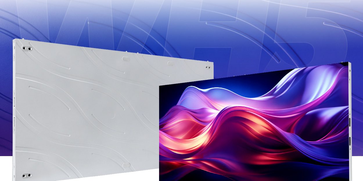
A flush-mounted front-service LED wall needs an approved cabinet grid, a coordinated wall section and a demonstrated component-removal path. A thin cabinet helps, but its depth does not define the whole recess. Confirm the mounting, cable route, trim, cooling and room-side working area before the joinery or wall opening is fabricated.
For corporate feature walls and briefing spaces, the architectural finish and the AV system must use the same dimensions. This guide develops a conditional 3.0 × 1.5 m EA250WH5 layout and a recess coordination worksheet. It complements a general maintenance guide with a specific cabinet, module and installed-depth planning example.
- Elevation: active display, cabinet grid, module grid and finished opening.
- Section: display-face datum, support, connectors, trim and thermal detail.
- Service plan: removal direction, tools and access for each replaceable component.
On this page
Set the finished face and fixing datum
State what “flush” means on the drawing: the LED face aligned with the surrounding wall finish, a small deliberate reveal, or a display set back inside a niche. Mark the structural fixing plane separately. A contractor measuring from unfinished plasterboard and another measuring from completed stone can otherwise approve different depths while using the same nominal recess size.
Survey the existing wall for level, flatness, obstructions and available support. Let the responsible project team approve the structure and fixing arrangement for the complete assembly. Do not use the screen cabinet’s published weight as the total load of the frame, cables and associated equipment.
Build a cabinet schedule before the recess
The EA250WH5 indoor LED wall uses 250 × 250 mm modules. Its published cabinet formats are 500, 750 and 1000 mm widths in 250 or 500 mm heights. Choose whole cabinet and module increments first, then coordinate the finished opening and permitted adjustments with the supplier.
Consider a proposed 3.0 m-wide by 1.5 m-high active wall using the 1000 × 500 mm format. The following is a planning calculation based on the published family dimensions, not an approved project drawing or a completed corporate installation.
| Item | Conditional calculation | Planning result |
|---|---|---|
| Active area | 3.0 × 1.5 m | 4.5 m² |
| Cabinets | 3 across × 3 high | 9 nominal 1000 × 500 mm cabinets |
| Module grid | 12 across × 6 high | 72 nominal 250 × 250 mm modules |
| Native pixels at P2.5 | 3000 ÷ 2.5 by 1500 ÷ 2.5 | 1200 × 600 pixels |
| Cabinet mass reference | 9 × published 10.5 kg | 94.5 kg of cabinets; excludes support and other equipment |
Confirm the active dimensions, exact pixel map and weight of the offered configuration in the order documents. This example is a 2:1 canvas. A 16:9 presentation should be prepared with an agreed crop, border or layout; stretching it to fill the wall changes its proportions. Check the smallest required charts and labels on the quoted pitch before choosing it.
Separate cabinet depth from installed depth
The EA250WH5 page lists a 30 mm cabinet depth. That is a product reference, not permission to make a 30 mm cavity. Request the net mounting stand-off required by the coordinated support, cable, connector, adjustment and thermal detail.
Depth from the LED face to the structural fixing plane = cabinet depth + the net stand-off required by the approved installation detail.
For this cabinet family, start with the published 30 mm cabinet figure, then obtain the remaining project-specific dimension. Do not add overlapping cable and frame spaces twice, or omit them because both trades assumed the other had allowed for them.

| Section item | Required confirmation | Common coordination error |
|---|---|---|
| Fixing and support | Approved mounting detail and structural plane | Sizing the recess from the LED cabinet alone |
| Cables and connectors | Entry direction, bend and termination space | A connector fouls the backing after the wall closes |
| Alignment adjustment | Accessible adjustment range and final face datum | The face cannot be made level with completed finishes |
| Thermal detail | Permitted enclosure and heat-removal arrangement | Decorative trim closes an intended heat path |
| Finished opening | Coordinated tolerances, reveal and removable trim | The opening fits nominal width but traps edge modules |
Test the opening with final trim in place
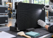
The product page describes front access to modules, power supplies and control components, using a suction tool. Validate that access in the installed condition. A loose cabinet on a workbench does not reveal whether the upper edge, return trim or adjacent wall finish will obstruct the actual service tool.
Use a representative built section with the proposed support and trim. Demonstrate a centre module, an edge module and the most constrained corner. Also identify the route for the largest internal component that must be removed. Have trained personnel use the exact approved tools and isolation procedure; a black picture does not establish electrical isolation.

Record which trim pieces must come off, where a removed module is supported and how the area is controlled during work. Preserve the required room-side work zone in the furniture plan. A reception desk, lectern or glass partition added after installation can defeat an otherwise valid service design.
Coordinate cooling, controls and handover
Agree the display’s operating brightness, content and hours with the thermal and electrical design. The cabinet’s indoor operating specification does not prove that an enclosed wall pocket will remain within it. Require the selected installation’s cooling arrangement and an agreed commissioning check rather than a universal recess or vent dimension.
Place external controllers, power distribution and network equipment where their own service requirements can be met. Label their connection to the cabinet grid. Front access to the LED modules does not make a hidden junction above a sealed ceiling accessible.
At handover, retain the as-built elevation and section, cabinet and module schedule, approved service tool, compatible spare identifiers, configuration backup and post-replacement image check. For routine work after acceptance, refer to the front-service module maintenance guide. This article’s model-specific grid and depth worksheet should remain with the project drawing set.
Flush-mounted front-service LED wall FAQ
Does a 30 mm LED cabinet fit a 30 mm wall recess?
The cabinet depth alone cannot establish the finished recess. Coordinate the mounting stand-off, cables, connectors, adjustment, thermal detail and wall datum on a section drawing. Confirm the selected cabinet and installed geometry before fabricating the opening.
How many EA250WH5 cabinets form the 3 by 1.5 metre example?
Using nominal 1000 by 500 mm cabinets gives three columns and three rows: nine cabinets and 4.5 square metres. The 250 by 250 mm module grid is 12 by 6, or 72 modules. This excludes installation tolerances, trim and any project-specific changes.
Can permanent trim overlap the edge of a front-service LED wall?
Only where the approved drawing and service demonstration permit it. Check the removal path of edge and corner modules, the service tool and every internal component. An attractive trim detail can obstruct maintenance even when the centre module is easy to remove.
Can a front-service cabinet eliminate the rear service corridor?
It can remove the need for rear access to the components that are genuinely front-serviceable. External controllers, power distribution, cable junctions and building services still need their own accessible locations and documented maintenance routes.
Request a coordinated wall specification
Send the desired active size, finished opening, wall section, structural fixing plane, viewing distances, content examples and installation city. Include trim, available front work space and proposed equipment locations. Ask for a cabinet schedule, coordinated section and service demonstration against the same revision.
Prepared by EagerLED for corporate-wall integrators. Product references reviewed on 15 October 2026. The cabinet, mass and pixel example is conditional planning arithmetic; it excludes support, tolerances and other equipment. Obtain the project-specific approved drawings and supplied configuration.