

An LED screen cube needs a face map, a playback plan and a repeatable acceptance test before its content can wrap convincingly around the structure. Treating each side as an ordinary screen often produces a cube that looks correct in still photographs but reveals reversed faces, mistimed transitions or a broken closing seam when visitors walk around it.
This guide helps showroom AV integrators coordinate four vertical faces, with an optional top face, from the creative brief through commissioning. It includes a worked pixel example, a face assignment table and practical checks for motion, corners and maintenance. Final cabinet selection, structural design and controller capacity still need confirmation for the actual installation.
1. Define the LED Screen Cube Faces and Viewing Routes
Start with a floor plan and name each visible surface. Use A, B, C and D for the vertical faces, proceeding clockwise when viewed from above. Label a top display T if the design includes one. Mark the entrance, the main demonstration position and the route that visitors follow. Attach the same labels to drawings, content templates and equipment schedules.
A showroom LED screen cube may be visible from several directions, but each viewer sees only part of it. Place essential information on a complete face that can be read from a normal standing position. A product name divided across three sides requires the visitor to move simply to understand it. Reserve continuous wraparound graphics for motion, patterns and visual storytelling.
Determine whether the top is a working display, an access opening or a non-display finish. These are different specifications. A fifth illuminated surface changes content layout, pixel load and the maintenance arrangement. It also introduces four additional edges to inspect. Do not add it late as a cosmetic detail after the signal and structure designs are approved.
Record the practical viewing distances and ambient lighting in the site survey. Include photographs from the doorway and demonstration positions. These observations help the content designer choose text size and safe areas without pretending that one pixel pitch guarantees readability at every angle.
2. Choose Continuous or Independent Playback
Decide what the audience should experience before choosing how many players to buy. An LED screen cube can carry one continuous visual, different messages on each face, or a timed combination of both. Each mode creates a different responsibility for the content designer and commissioning team.
| Mode | Useful application | Main design task | Acceptance evidence |
|---|---|---|---|
| Continuous wrap | A ribbon, landscape or animation crossing faces | Create a consistent face order and join the final face back to the first | A moving marker crosses every vertical edge without a visible jump |
| Independent faces | Separate product families or languages | Give each face a complete composition and readable message | Correct content appears on each labelled face after restart |
| Coordinated scenes | A launch sequence with separate face layouts | Agree common cue points and transition duration | All faces change scene together throughout repeated playback |
Independent content does not require independent clocks. A single composition can contain four different face designs while sharing one timeline. Conversely, four devices that start at approximately the same time do not automatically provide lasting synchronization. Ask the integrator to explain the timing method and demonstrate it under the intended operating conditions.
For an LED screen cube that alternates between modes, define the transitions as part of the creative brief. Agree whether a wraparound sequence fades into four separate layouts or changes on a shared cue. Check the longest intended program, including its loop boundary. A short demonstration may hide drift or a discontinuity that appears only when the playlist restarts.
3. Calculate the Native Canvas Before Rendering
Use confirmed module and cabinet pixel counts for the final content template. Physical dimensions divided by a rounded pitch label are useful for an estimate, but they can produce the wrong exact resolution. A content agency needs integer pixel dimensions, not a nominal pitch and a photograph.
01. Work from the cabinet matrix
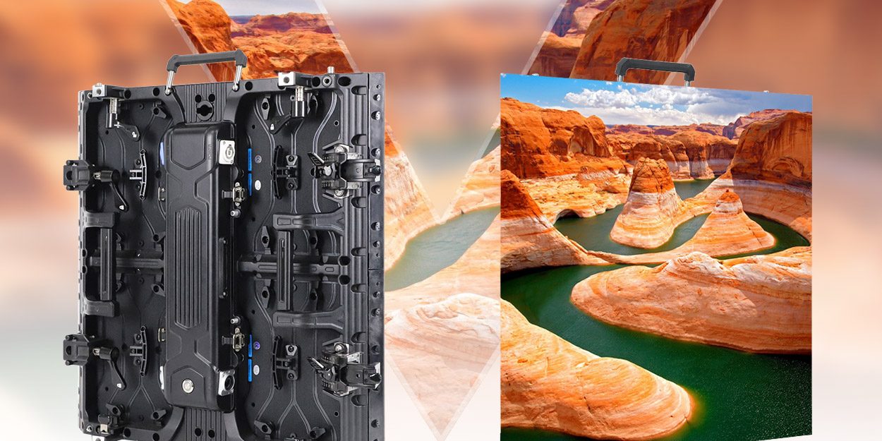
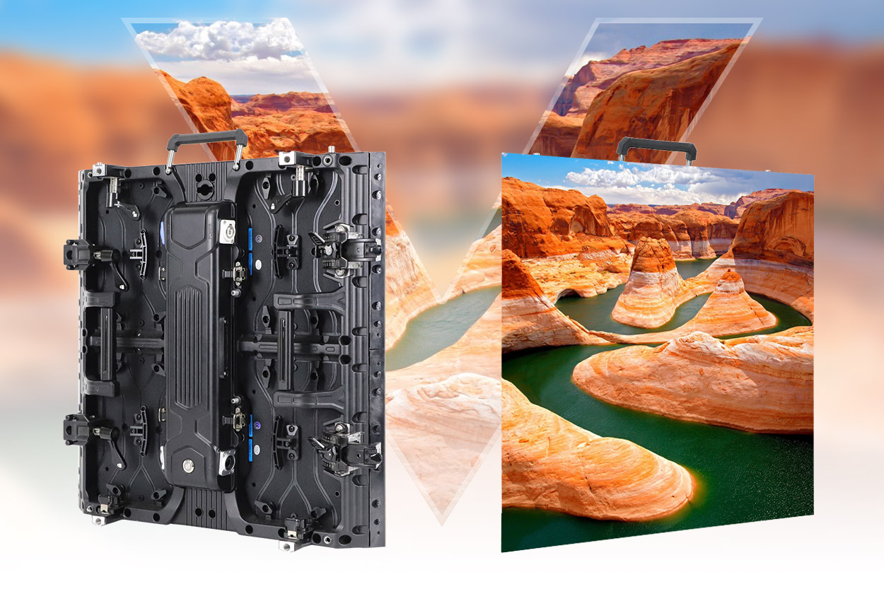
The EA500H8V product specification lists 500 × 500 mm cabinets with four 250 × 250 mm modules. Its indoor P2.97 entry lists 84 × 84 pixels per module. For that specified arrangement, two modules across and two high give 168 × 168 pixels per cabinet.
As a planning example, a face four cabinets wide and four high would measure 2 × 2 meters and contain 672 × 672 pixels. Four such vertical faces contain 1,806,336 pixels altogether. An unwrapped horizontal strip would therefore be 2,688 × 672 pixels. This is a content calculation for an illustrative arrangement, not confirmation that a particular controller or structure supports the complete build.
02. Separate content size from transport size
The native LED screen cube canvas and the computer’s video output do not always have the same dimensions. A media system may place the native canvas within a larger supported output format. In that case, document the active region and unused padding. Check maximum input width, height, total loading and output-port limits separately with the proposed hardware.
Adding an equally sized top face increases the example’s active pixel total to 2,257,920. It does not mean that stretching the original four-face strip will work. The LED screen cube template must give the top its own region and orientation. Ask for a labelled test image in the exact delivery format before commissioning the final animation.

4. Build a Face Assignment Map Everyone Can Read
The LED screen cube map should connect three things: the physical surface, its region in the source canvas and its destination in the control system. Keep the face labels stable even if an installer changes a cable route. Otherwise, a content revision can silently follow an outdated wiring convention.
| Face | Source origin X, Y | Region size | Orientation check | Next vertical edge |
|---|---|---|---|---|
| A: entrance | 0, 0 | 672 × 672 | Arrow up; text reads normally | Right edge joins B left |
| B: clockwise from A | 672, 0 | 672 × 672 | Arrow up; text reads normally | Right edge joins C left |
| C: opposite A | 1,344, 0 | 672 × 672 | Arrow up; text reads normally | Right edge joins D left |
| D: clockwise from C | 2,016, 0 | 672 × 672 | Arrow up; text reads normally | Right edge returns to A left |
These coordinates use a top-left origin and describe source regions only. They are not port numbers or receiving-card settings. Add the actual output, port, cabinet path and configuration-file reference in a separate installation column after the hardware design is confirmed. Leave no ambiguity about whether a drawing shows the display from the front or from inside the structure.
A useful LED screen cube test image contains large face letters, an upward arrow, differently colored corners and horizontal lines that meet at matching heights. This catches rotation and mirroring mistakes immediately. Number small blocks near the edges if you need to detect missing or duplicated pixel columns.
Resolume’s official Advanced Output and Input Selection documentation describes selecting portions of a composition and mapping those regions to outputs. That illustrates the distinction between source selection and physical output mapping. The exact controls depend on the selected software and version; supply the finished preset as well as a readable diagram.
For a five-face LED screen cube, define which edge of the top touches face A and mark that edge in the template. A top-view drawing and an unfolded drawing can appear to disagree when their viewing directions are unclear. Put a unique symbol at each top corner, then verify the four symbols from the agreed viewing position. Do not rotate the entire master canvas to fix one incorrectly oriented surface.
5. Keep Timing Consistent Across the Signal Path
A coordinated LED screen cube needs consistent timing from media playback through processing to the receiving system. A high LED refresh-rate specification alone does not establish that separate players or processors show the same source frame. Keep source frame rate, output timing and display refresh specifications distinct in the equipment schedule.
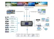
Begin with the simplest signal arrangement that meets the project requirements. Where one player and one compatible processing path can handle the canvas, they can reduce the number of independent timing points to manage. Larger designs may need multiple outputs or processors. Those require a documented synchronization arrangement, not an assumption based on matching model names.
Test the LED screen cube with a moving bar and visible frame numbers across adjacent faces. Watch the physical edges during motion and scene changes. If the bar separates at one edge, investigate source timing, processing latency and mapping before changing the artwork. Use camera footage to document behavior, while recognizing that camera shutter effects can create artefacts of their own.
Include a restart test. Verify the selected resolution, refresh timing, content region and face assignments after the player and display system return to operation. Also test the agreed response to a missing source. A defined holding image or controlled blackout is easier for showroom staff to understand than an unexplained frozen fragment on one side.
When a fault appears, preserve the approved LED screen cube preset before troubleshooting. A stationary line that fails to meet suggests a coordinate, scaling or physical alignment problem. A line that meets when paused but separates during movement points toward a timing issue. A correct test grid with a broken promotional sequence points back toward the content export or creative layout. These observations narrow the investigation; they do not replace hardware diagnostics. Change one relevant setting at a time and record the result.

6. Check Every Corner, Including the Closing Seam
A four-sided LED screen cube has a closing seam between D and A that is easy to miss on a flat content preview. A long panoramic image may look correct across A–B, B–C and C–D but break when its final column meets its first. Ask the content designer to preview that connection explicitly.
Use two separate checks. First, inspect the physical join for alignment, gaps, damaged edge pixels and an uneven cabinet plane. Second, inspect the content join with matching test lines and moving objects. Software can correct a mapping error, but stretching artwork to conceal a mechanical mismatch can distort every face.
Judge the LED screen cube from the normal visitor route as well as directly in front of each face. A seam that is acceptable head-on may become prominent at an oblique angle. Compare white, grey and low-brightness material under the agreed showroom lighting. Record the viewing positions and operating brightness so later comparisons are meaningful.
Keep text, logos and small critical details away from edges unless the design specifically requires them to cross. Agree the safe area using a physical sample or full-scale test. A generic margin percentage cannot account for every pitch, viewing distance and corner construction. For the underlying cabinet geometry, refer to the right-angle display design guide.

7. Plan Maintenance Without Losing the Face Map
Decide how a technician reaches modules, receiving cards, power supplies and cables before enclosing the structure. An LED screen cube can hide all of its rear surfaces inside a compact volume. Front-removable modules help, but the team must still demonstrate access to the parts behind them and a safe removal sequence.
EA500H8V product information describes front and rear service arrangements. Confirm the proposed cabinet version, corner position and support structure together. A service feature on an individual cabinet does not prove that a technician can remove it after adjacent faces, trims and structural members are installed.
Give every replaceable position a face-and-location label. For example, A-R2-C3 identifies a cabinet by face, row and column, provided the numbering direction appears on the drawing. Store the corresponding receiving configuration and calibration information with the installation records. A replacement that lights up still needs checks for orientation, color and correct address mapping.
For the LED screen cube recovery plan, retain the approved media files, player project, output preset and controller configuration as distinct items. Record versions and dates. Restrict routine operators to the controls they need for daily playback, and provide a clear support route for changes to mappings or hardware settings.

8. Agree Acceptance Evidence Before Delivery
Approve the LED screen cube against named tests, not just a promotional video. The factory test should use the agreed face layout and representative content. The site test should repeat the key checks after transport, assembly and connection to the actual playback system. Structural and electrical acceptance should be handled by the responsible qualified professionals.
Use the following matrix as a starting point and add project-specific tolerances before purchase. It deliberately avoids universal limits for seam width or brightness mismatch: those need agreement against the selected hardware, installation and viewing conditions.
| Check | Test material or action | Record to keep |
|---|---|---|
| Face identity | Letters, upward arrows and colored corner marks | Photo showing each face in its correct physical position |
| Edge continuity | Grid and moving line across all joins | Results for A–B, B–C, C–D and D–A; top edges if fitted |
| Playback coordination | Frame counter and repeated scene changes | Test duration, output settings and observed timing differences |
| Visual consistency | White, grey and representative dark scenes | Lighting, brightness setting, viewing positions and agreed exceptions |
| Recovery | Controlled restart and source-loss test | Expected state, recovery sequence and responsible support contact |
| Service | Demonstrate access to a selected module and internal component | Access route, tools, configuration backup and recheck procedure |
Finish with an operator demonstration using the final playlist. Ask the showroom team to start the system, change an approved program and follow the documented recovery steps. Include the face map and test results in the display handover package. Keep unresolved items visible rather than allowing a successful first playback to close them automatically.
Frequently Asked Questions
Can an LED screen cube show different content on each side?
Yes, the design can assign a different composition to each face. Decide whether those compositions must share scene changes or can run independently. One master timeline can still contain separate face layouts, so different content does not by itself require multiple players.
Does every cube need six active faces?
No. Specify the actual display surfaces. Four vertical faces, or four faces plus a top, may suit a showroom. The remaining surfaces can serve structural, ventilation or access functions. Do not count a non-display surface in the content canvas.
How do I prevent a visible jump at the last corner?
Check the D-to-A join in both the artwork and the physical mapping. The end of a horizontal strip must connect to its beginning if the animation wraps continuously. Test a moving marker across that closing seam, not only the other three corners.
Will a high refresh rate guarantee synchronized faces?
No. LED refresh rate and synchronization between playback paths describe different things. Verify source frames, processing timing and the selected synchronization method. A full-system motion test provides more useful evidence than a single refresh-rate number.
What should the content agency receive before rendering?
Supply exact face resolutions, face order, viewing directions, rotations, safe areas and the delivery format. Include the top-face region if applicable. Approve a labelled test file on the real system before producing the complete animation.
Plan Your Showroom Cube with EagerLED
To scope an LED screen cube, share the intended face count, dimensions, viewing route and playback modes with EagerLED. Include the maintenance constraints and whether a top display is required. Send your project requirements to discuss cabinet options, control-system requirements and a testable delivery plan. You can also view product demonstrations on the official EagerLED video channel while preparing your brief.