

LED screen dead pixels are usually symptoms, not the whole fault. A single dark dot may indicate a failed lamp, while a row, block, or cabinet-sized outage often points to a driver, power, or data-path problem. This guide shows how to read the pattern, isolate the cause, select the least disruptive repair, and prevent the defect from returning.
Table of Contents
1. What Are LED Screen Dead Pixels?
2. Dead Pixels vs. Stuck Pixels vs. Weak Pixels
3. Common Failure Patterns and What They Reveal
4. What Causes LED Screen Dead Pixels?
5. How to Diagnose LED Screen Dead Pixels
6. How to Repair LED Screen Dead Pixels
7. How to Prevent LED Screen Dead Pixels
8. How EagerLED Supports Long-Term Display Reliability
9. FAQs
10. Conclusion
1. What Are LED Screen Dead Pixels?
On a direct-view LED display, each pixel contains red, green, and blue light-emitting elements. The controller varies those three channels to reproduce color and brightness. LED screen dead pixels appear when one or more elements cannot respond correctly, leaving a dark, discolored, or dim point in the image.
1.1 A pixel can fail at more than one level
The visible pixel sits at the end of a chain: controller, sending card, receiving card, hub board, driver IC, printed circuit board, solder joints, and LED package. A fault anywhere in that chain can imitate a dead pixel. This is why technicians should diagnose the size and shape of the outage before touching the module.
1.2 Why fine-pitch displays expose defects faster
Fine-pitch displays are viewed from shorter distances and contain more pixels in the same area. One failed point therefore interrupts an otherwise smooth surface and becomes easy to notice on solid colors, logos, and skin tones. Even a low defect count can matter in control rooms, studios, showrooms, and broadcast environments.
1.3 Permanent failure or temporary symptom?
A lamp with an open circuit is a permanent hardware failure. A loose ribbon cable, unstable power rail, incorrect mapping file, or overheated driver can create an intermittent symptom. Before classifying LED screen dead pixels as permanent, confirm that the same locations fail on multiple test patterns and after the signal path has been checked.

2. Dead Pixels vs. Stuck Pixels vs. Weak Pixels
Not every abnormal point is dead. The fastest first decision is to identify whether the pixel is dark, fixed to one color, or simply dimmer than its neighbors.
| Fault type | Typical appearance | Likely source | Best first action | Usual repair |
|---|---|---|---|---|
| Dead pixel | Black on every test pattern | Failed LED package, open solder joint, damaged pad | Confirm with red, green, blue, and white patterns | Replace the lamp or module |
| Stuck pixel | Always red, green, blue, cyan, magenta, or yellow | Sub-pixel short, driver output fault, control-data error | Run local self-test and verify configuration | Repair the driver circuit or replace the lamp/module |
| Weak pixel | Correct color but lower brightness | Aging, current imbalance, heat stress, poor contact | Compare at several brightness levels | Calibrate if uniform; replace hardware if isolated |
| Intermittent pixel | Flickers or changes when the cabinet moves or warms | Cracked solder joint, loose connector, marginal driver | Inspect while monitoring temperature and vibration | Resolder, reseat, or replace the affected part |
2.1 Why software “pixel fixer” videos rarely solve LED walls
Rapidly changing colors may help expose a marginal signal or control problem, but they cannot reconnect an open LED junction or repair damaged solder. That advice is often aimed at LCD panels, where the failure mechanism is different. Persistent LED screen dead pixels on a modular video wall normally require electrical diagnosis and hardware service.
2.2 A practical rule
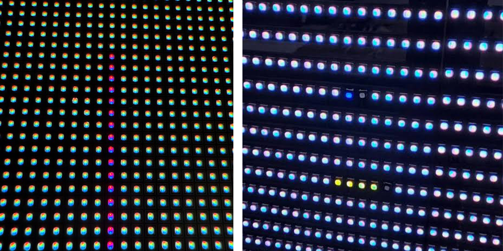
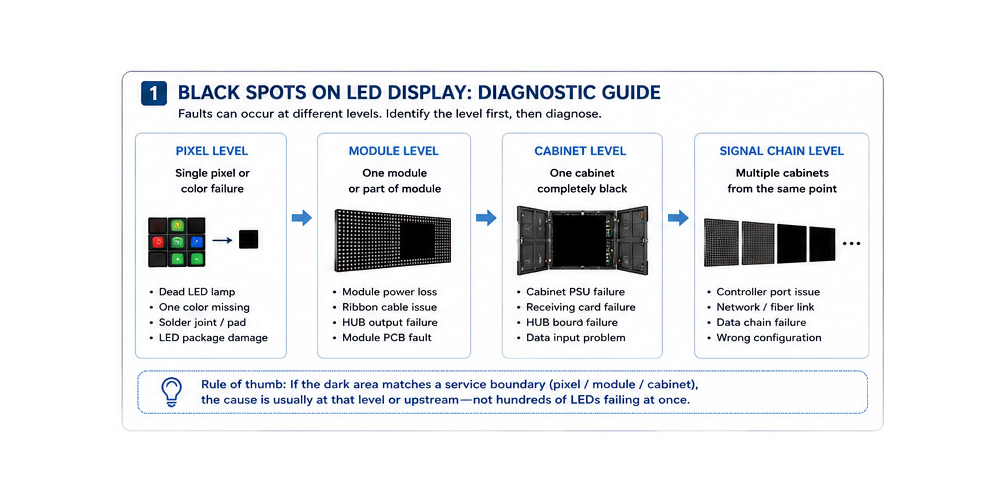
If one point fails while surrounding pixels work, suspect the lamp or its local solder connection. If an exact row, column, block, module, or cabinet fails, start upstream. Hundreds of LEDs rarely fail simultaneously in a perfect geometric boundary.
3. Common Failure Patterns and What They Reveal
The outline of the dark area is a diagnostic shortcut. It helps distinguish genuine LED screen dead pixels from larger power and signal faults before parts are removed.
3.1 One dark point or one missing color
A single black point on all patterns usually indicates a failed LED package, lifted pad, or open joint. If the point turns red but not green or blue, only one color channel has failed. Mark the location, record the module coordinates, and confirm that the symptom stays in place.
3.2 A straight row or column
A clean horizontal or vertical line suggests a driver IC output, scan-line, address, or PCB trace problem. Replacing every lamp in that line would treat the symptom rather than the cause. Inspect the corresponding driver pins, resistors, solder joints, and traces.
3.3 A rectangular block
A block often follows a scan group or driver boundary. Compare the shape with the module schematic. If the same block changes when a ribbon cable is reseated, the data path is more likely than multiple LED screen dead pixels.
3.4 One full module or cabinet
A completely dark module points to its power connector, fuse, hub output, or data cable. A cabinet-sized outage points to a receiving card, power supply, upstream network port, or configuration issue. For a wider symptom, follow the data chain from the last working cabinet to the first dark one.
4. What Causes LED Screen Dead Pixels?
Most faults come from component quality, assembly stress, electricity, heat, moisture, or handling. In real installations, two factors often combine; for example, high temperature can weaken a solder joint that later opens during transport.
4.1 LED package and semiconductor failure
The light-emitting junction can fail because of an internal defect, electrical overstress, contamination, or long-term thermal stress. Package construction also affects mechanical strength and moisture resistance. For a deeper look at SMD, COB, GOB, and related methods, see EagerLED’s LED packaging technology guide.
4.2 Solder joints, pads, and PCB traces
Insufficient solder, excessive reflow heat, a lifted pad, or a hairline PCB crack can interrupt current. Rental screens face extra risk because repeated assembly and transport flex connectors and modules. Intermittent LED screen dead pixels that react to movement are strong evidence of a connection problem.
4.3 Electrostatic discharge
Static electricity can damage LEDs and driver outputs during production or service, sometimes without an immediate visible mark. Use grounded workstations, wrist straps, anti-static packaging, and ESD-safe tools. The ESD Association explains how charge accumulation and discharge damage electronic devices.
4.4 Heat and current stress
Excess temperature accelerates material aging, changes electrical behavior, and stresses solder interfaces. Blocked ventilation, dust buildup, overloaded power supplies, excessive brightness, and poor cabinet design raise the risk. The U.S. Department of Energy’s LED basics overview also notes that thermal management is central to LED performance and lifetime.
4.5 Moisture, corrosion, and contamination
Water ingress and condensation can corrode pads, connectors, and traces. Coastal salt, conductive dust, smoke residue, and chemical vapors make the problem worse. Outdoor cabinets need intact seals, drainage, suitable ingress protection, and dry internal surfaces before power is applied.
4.6 Power, driver, and signal faults
Voltage drop, an aging power supply, a damaged hub board, corrupted configuration, or a loose data cable can mimic LED screen dead pixels. When the fault follows a service boundary, verify power and data before replacing lamps.
5. How to Diagnose LED Screen Dead Pixels
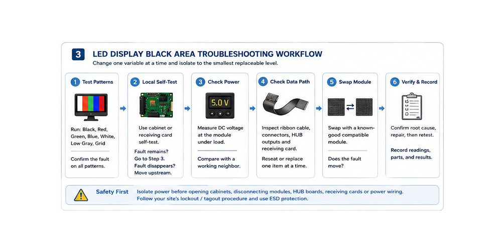
A disciplined workflow changes one variable at a time. It prevents a technician from replacing a module only to discover that the original fault was a cable or receiving card.
5.1 Make the screen safe
Only trained personnel should open cabinets or perform component-level work. Isolate power, follow the site’s lockout/tagout procedure, confirm that stored energy has discharged, and use ESD protection. Never connect or remove powered modules unless the manufacturer explicitly supports that procedure.
5.2 Clean and inspect before testing
Dust, debris, a damaged mask, or surface contamination can look like a dark point. Inspect from normal viewing distance and up close. Photograph the defect, note the cabinet and module position, and check for impact marks, water traces, discoloration, or loose connectors.
5.3 Run solid-color patterns
Display black, red, green, blue, white, and mid-gray. True LED screen dead pixels remain dark on every illuminated pattern. A stuck channel appears on specific colors, while a weak pixel becomes more obvious at low or medium brightness. Test patterns also reveal whether the problem follows a row, scan group, or module boundary.
5.4 Compare local self-test with the live signal
Use the receiving card or cabinet self-test when available. If the defect appears during local self-test, the problem is inside the cabinet or module. If local self-test is clean but the live image fails, inspect the controller, mapping file, network link, and upstream configuration.
5.5 Check power under load
Measure at the module input while displaying a high-load pattern and compare the reading with a known-good neighboring module. A no-load reading can look normal even when a poor connector drops voltage under current. Follow the screen manufacturer’s specified voltage and tolerance; do not apply a generic value.
5.6 Reseat, swap, and isolate
With power safely isolated, inspect and reseat data and power connections. Swap only one known-good compatible part at a time. If the fault moves with the module, the module is responsible. If it stays in the cabinet position, continue upstream. This method turns a vague report of LED screen dead pixels into a confirmed replaceable level.
5.7 Record the result
Log screen coordinates, test patterns, voltages, temperatures, swapped parts, root cause, and final verification. A fault history shows whether failures cluster by batch, cabinet location, heat zone, or environmental exposure.
6. How to Repair LED Screen Dead Pixels
The correct repair is the smallest replaceable level that removes the verified cause without creating color inconsistency or unnecessary downtime.
6.1 Reconfigure or replace the signal component
If local self-test passes, restore the correct receiving-card file, mapping, firmware, or controller configuration. Replace damaged network cables, hub boards, or receiving cards only after the fault has been isolated. This is the right fix when apparent LED screen dead pixels disappear during self-test.
6.2 Repair a connector, joint, trace, or driver
A qualified electronics technician may reseat a connector, resolder a cracked joint, repair a trace, or replace a driver IC. The work requires the correct schematic, temperature-controlled equipment, magnification, ESD controls, and post-repair testing. Improvised soldering can lift pads or damage nearby LEDs.
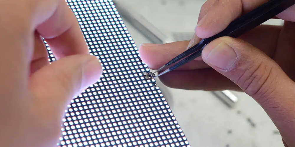
6.3 Replace one LED lamp
For an isolated package failure, lamp replacement preserves the rest of the module. The replacement must match package type, polarity, electrical characteristics, color bin, and brightness. Fine-pitch products demand precise alignment and thermal control; inexperienced rework can create more LED screen dead pixels than it removes.
6.4 Replace the complete module
Module replacement is often faster when several faults cluster together, the PCB is damaged, or pixel-level work would take too long on site. Use a calibrated spare from the same production batch when possible. After installation, correct brightness and color differences through approved calibration rather than hiding them with excessive global adjustment.
6.5 Know when to escalate
Escalate when failures repeat after repair, affect multiple cabinets, involve water or burned components, or exceed the team’s training and equipment. Repeated faults often indicate a systemic problem such as heat, power quality, sealing, or handling. EagerLED can help customers compare symptoms, test results, and spare-part options before a broader replacement decision.
7. How to Prevent LED Screen Dead Pixels
Prevention starts before installation and continues through operation. The objective is to reduce mechanical, electrical, thermal, and environmental stress while making early faults easy to find.
7.1 Specify dependable components and packaging
Choose proven LED lamps, driver ICs, power supplies, connectors, and PCBs. Match the packaging method to viewing distance, impact exposure, and environment. EagerLED’s guide to selecting LED lamp beads explains the quality factors that influence brightness, color consistency, and reliability.
7.2 Verify factory quality control
Incoming inspection, automated optical inspection, controlled reflow, module testing, aging tests, and final pixel checks catch early defects. Ask the supplier how faults are recorded and corrected, how spares are matched, and what acceptance criteria apply. These controls reduce early-life LED screen dead pixels.
7.3 Control heat and electrical load
Keep ventilation paths clear, clean filters and fans, monitor cabinet temperature, and avoid running unnecessary maximum brightness. Balance power distribution and investigate hot connectors or supplies promptly. A thermal trend is more useful than a single spot reading because it reveals gradual deterioration.
7.4 Keep moisture out
Inspect door seals, cable glands, drainage paths, coatings, and fasteners. After storage or rapid temperature change, allow equipment to reach a safe dry condition before energizing it. Do not seal existing moisture inside a cabinet.
7.5 Use ESD-safe handling and transport
Ground technicians and work surfaces, store modules in anti-static packaging, protect corners and connectors, and never stack modules on LED faces. Rental teams should inspect after every transport cycle because impact and flexing can create latent failures.
7.6 Build a maintenance baseline
At commissioning, save test-pattern photos, calibration files, receiving-card configurations, voltage readings, and thermal measurements. Repeat the same checks on a schedule. A baseline makes new LED screen dead pixels obvious and helps technicians act before faults spread.
7.7 Keep compatible spares
Store matched modules, power supplies, receiving cards, hub boards, and cables in a dry, labeled, ESD-safe environment. Record batch and calibration information. The best spare is not merely the same pixel pitch; it must also match mechanical, electrical, optical, and control requirements.
8. How EagerLED Supports Long-Term Display Reliability
A maintainable display is designed around access, documentation, matched spares, and a clear diagnostic path. EagerLED supplies indoor, outdoor, rental, and fine-pitch LED display solutions with attention to module construction, cabinet service access, thermal design, and application conditions.
8.1 Select the screen for the real environment
Viewing distance is only one input. Brightness, humidity, salt exposure, dust, operating hours, service access, transport frequency, and mounting all influence reliability. Sharing these conditions early helps the supplier recommend suitable protection and maintenance provisions.
8.2 Plan spares and service before commissioning
Confirm spare quantities, storage conditions, module matching, front or rear access, and responsible technicians. When LED screen dead pixels appear, this planning shortens diagnosis and avoids installing an optically mismatched spare under time pressure.
8.3 Use related troubleshooting resources
If the symptom is a larger dark area, use the black spots on display guide. If the whole screen or a signal section is dark, follow the LED black screen troubleshooting guide. These pages separate pixel-level faults from module, cabinet, and system-level failures.
9. FAQs
9.1 Can LED screen dead pixels be fixed?
Yes. A failed lamp can be replaced by a qualified technician, while a damaged module can be swapped. However, the visible point may come from a driver, solder, power, or signal fault, so diagnosis should come before replacement.
9.2 Do flashing-color pixel fixers work on LED video walls?
They can expose a temporary data or driver symptom, but they cannot repair an open LED junction, cracked solder joint, corroded trace, or failed component. Persistent hardware faults require service.
9.3 How do I test for LED screen dead pixels?
Run full-screen red, green, blue, white, black, and gray patterns. Record points that stay dark, fixed-color, or dim. Then compare cabinet self-test with the live input to separate local hardware from upstream signal issues.
9.4 Should I replace a lamp or the whole module?
Replace one lamp when the failure is isolated and skilled rework is available. Replace the module when faults cluster, the board is damaged, downtime matters more than bench-repair cost, or fine-pitch rework would be risky.
9.5 How can I reduce repeat failures?
Control heat and moisture, use ESD-safe handling, maintain stable power and data connections, inspect after transport, keep matched spares, and track fault locations. Repeated LED screen dead pixels in one area usually indicate a shared environmental or system cause.
10. Conclusion
LED screen dead pixels are easiest to solve when the outage pattern guides the diagnosis. Test solid colors, compare local self-test with the live signal, verify power and data, then repair the smallest confirmed level. Reliable components, thermal control, moisture protection, ESD-safe handling, matched spares, and recorded maintenance prevent isolated defects from becoming recurring downtime.